Rotary Engine

a technology of rotary engine and piston engine, which is applied in the direction of positive displacement engine, reciprocating piston engine, machine/engine, etc., can solve the problem of dictating a high production cost burden, and achieve the effect of low production cost, low production cost, and simple structur

Inactive Publication Date: 2010-05-06
MARBAW INT NICKEL CORP
View PDF12 Cites 9 Cited by
  • Summary
  • Abstract
  • Description
  • Claims
  • Application Information

AI Technical Summary

Benefits of technology

[0007]It is a further object of the present invention to propose such an engine in which there are unique constructional and operational elements at an economic manufacturing cost, resulting in reliability and efficiency available to consumers at a competitive and affordable price.
[0008]A still further object of the present invention is to provide a rotary engine of essentially modular construction, thus allowing of ease of replacing parts and interchangeability. Additionally, the modular construction affords versatility in power train design and function.
[0009]Moreover, an important object of the present invention is to provide a rotary engine with enhanced balance, low friction and low noise output.

Problems solved by technology

However, cost is an important factor and generally with commercially produced units, the degree of sophistication dictates a high production cost burden reflected in the selling price.

Method used


Image

  • Rotary Engine
  • Rotary Engine
  • Rotary Engine

Examples


Embodiment Construction

[0038]With reference to the annexed drawings the preferred embodiments of the present invention will be herein described for indicative purpose and by no means as of limitation.

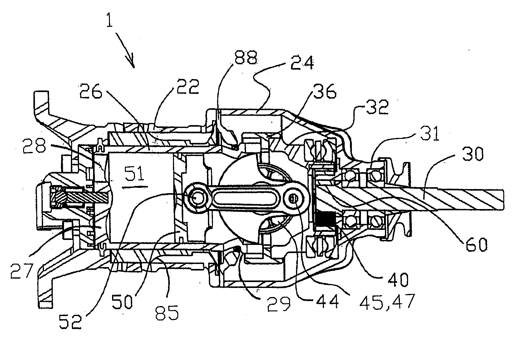
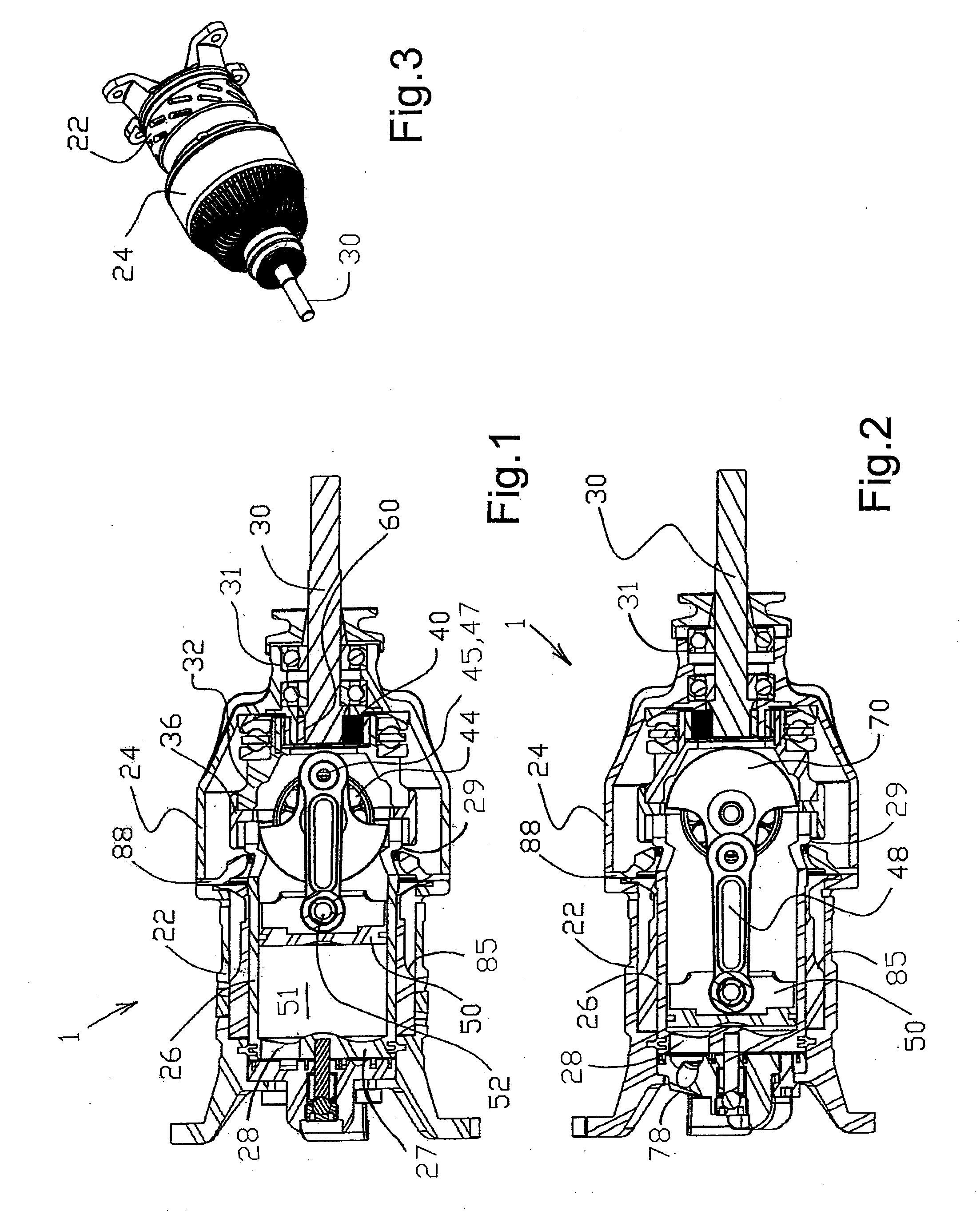
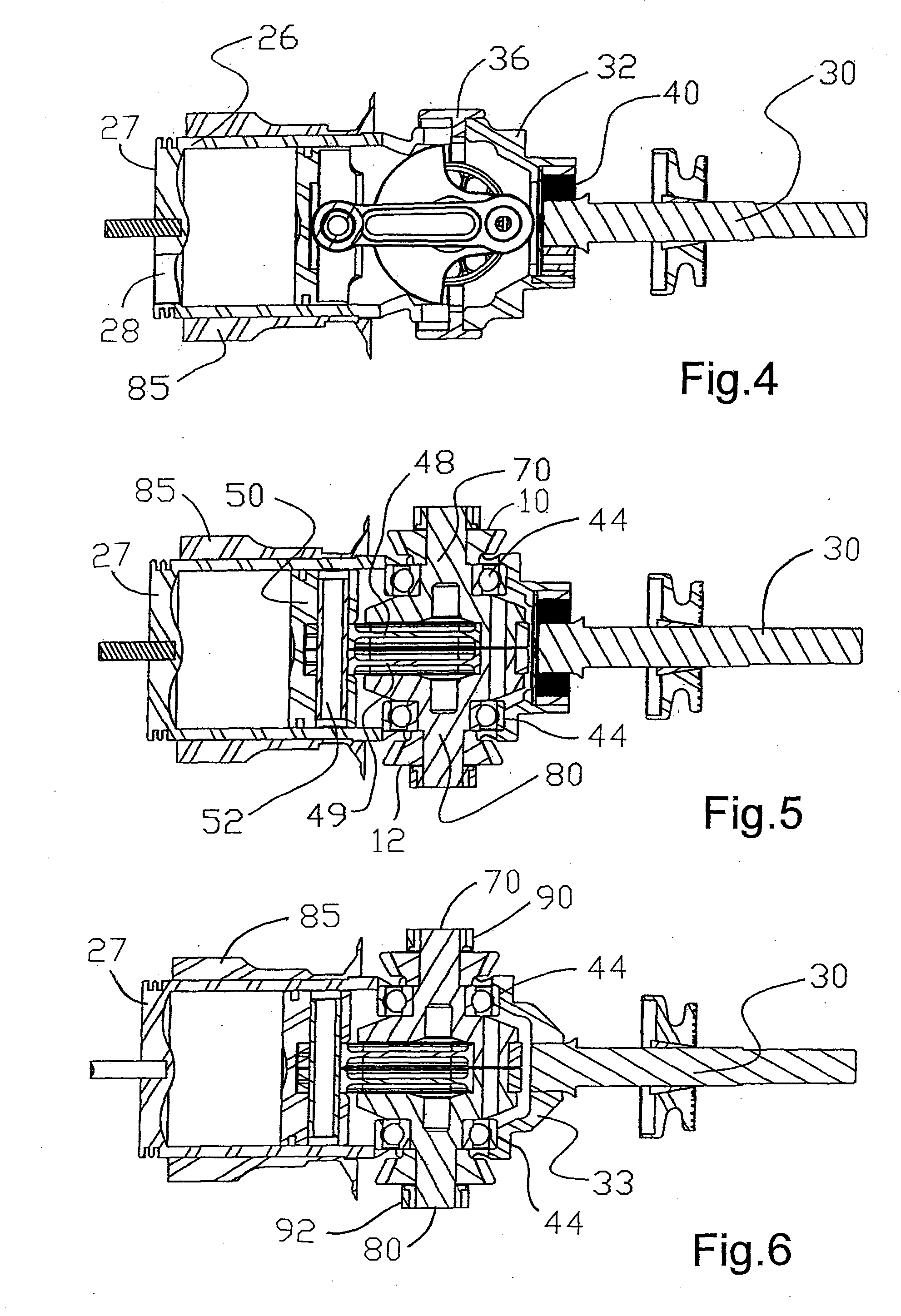
[0039]Reference is now made to FIGS. 1 and 2 in which a rotary engine in accordance with an embodiment of the present invention is shown generally at 1 and comprises a cylinder or engine casing 22 accommodating within its cavity a rotatable cylinder 26 provided with cooling fins 85 which are a snug fit to ensure smooth rotary movement of the cylinder 26 within the said cavity. The cylinder 26 is provided with a cylinder head 27 having a suitable aperture 28 as described hereinafter.

[0040]A crank casing 24 is attached to the cylinder casing 22, with a gear ring 88 therebetween, as shown and provides an outlet ball race 31 for an output shaft 30.

[0041]The cylinder 26 at its end remote from the head 27 forms a gear cage cradle 29 attaching to a gear cage cradle base 32 and a crankshaft outer support 36, the bear...


PUM


Abstract

A rotary engine (1) is characterised by a driven output shaft (30) powered by internal combustion carried out in a cylinder (26) to drive a piston (50) and crankshafts (70, 80) carrying contra-rotating drive gears (10, 12) meshing with a fixed gear ring (88), rotation of the gears (10, 12) transmitting rotary motion to the piston (50) and the cylinder (26), the gear cage base (32), gears (10, 12) and to the output shaft (30). The contra-rotation of the gears (10, 12) on the respective crankshaft (70, 80) provides for a balanced power transmission.

Description

FIELD OF THE INVENTION[0001]The present invention relates to internal combustion engines, and is more particularly concerned with such engines categorised as rotary engines.BACKGROUND OF THE INVENTION[0002]Conventional internal combustion engines employ one or more cylinders in each of which reciprocates a piston driven by the explosive power generated by the combustion of a fuel triggered by the use of either a spark or compression. The power so produced is used to drive a shaft for use in traction, for example in motor vehicles, or for static use in other machinery or indeed to produce more power, for example by the deployment of a generator.[0003]Various proposals have been made to vary this manner of operation, for example the Wankel Engine which uses one or more specially shaped rotors mounted on a drive shaft, fuel being combusted to provide the motive power to turn the rotor(s) to drive the shaft. Another example of a rotary engine was that used in some early military planes ...

Claims


Application Information

Patent Timeline
Patent Type & Authority Applications(United States)
IPC IPC(8): F02B75/26
CPCF01B1/01F01B3/00F02B59/00F02B75/16F02B75/26F01B1/10F01B9/02F01B15/007F02B75/065F02B57/00F02B75/32
Inventor ARSENEAU, MICHEL
Owner MARBAW INT NICKEL CORP
Why Eureka
Try Eureka