Permanent magnet motor and method for manufacturing same

a permanent magnet motor and permanent magnet technology, applied in the direction of rotating magnets, synchronous machines with stationary armatures, magnetic circuits characterised by magnetic materials, etc., can solve the problems of increasing torque ripple, decreasing torque, and decreasing remanence (bsub>r/sub>), so as to reduce vibration and noise, the effect of not decreasing the rotational torqu

Active Publication Date: 2010-05-06
HITACHI METALS LTD
View PDF12 Cites 28 Cited by
  • Summary
  • Abstract
  • Description
  • Claims
  • Application Information

AI Technical Summary

Benefits of technology

[0009]To overcome the problems described above, preferred embodiments of the present invention provide a permanent magnet motor that is highly resistant to a demagnetizing field, in which, although the use of a heavy rare-earth element RH that is a rare metal is reduced, the rotational torque is not decreased and the occurrence of vibration and noise is reduced, compared with the conventional motors.

Problems solved by technology

However, with the conventional technique, the decrease in remanence (Br) is still unavoidable.
For this reason, the remanence sharply changes in the enhanced-coercivity portion, and hence when used in a motor and the like, the magnet will cause problems such as decrease in torque, increase in torque ripple and resultant occurrence of noise.

Method used


Image

  • Permanent magnet motor and method for manufacturing same
  • Permanent magnet motor and method for manufacturing same
  • Permanent magnet motor and method for manufacturing same

Examples


example

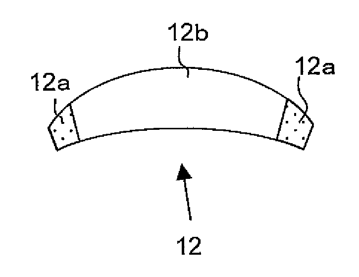
[0065]In this Example, the permanent magnet 12 in a shape shown in FIG. 5A is used. Dy is diffused in both end portions of the permanent magnet 12 as a sintered magnet body in the manner described in the above preferred embodiment. To state specifically, a base magnet (sintered magnet body) having a composition shown in Table 1 below is prepared, and 0.36 mass % of Dy is diffused in the end portions (specific regions) thereof, forming the high coercivity portions 12a. The coercivity HcJ of the base magnet is 1700 kA / m and the remanence Br thereof is 1.276 T (tesla), while the coercivity HcJ of the high coercivity portions 12a is set at 2024 kA / m and the remanence Br thereof at 1.264 T. In this way, with Dy diffused, the coercivity HcJ of the high coercivity portions 12a increases by about 300 kA / m compared with that of the base magnet, and the decrease in remanence Br is suppressed to 0.012 T.

TABLE 1ElementNdPrDyBCoAlCuFeComposition19.46.85.01.000.900.200.10balance[wt %]

[0066]The si...


PUM

PropertyMeasurementUnit
thicknessaaaaaaaaaa
sizeaaaaaaaaaa
mean particle sizeaaaaaaaaaa

Abstract

A permanent magnet motor includes: a rotor and a stator; and a plurality of permanent magnets placed on either the rotor or the stator. Each permanent magnet is an R—Fe—B based rare-earth sintered magnet including a light rare-earth element RL (at least one of Nd and Pr) as a major rare-earth element R, and partially includes a high coercivity portion in which a heavy rare-earth element RH (at least one element selected from the group consisting of Dy, Ho and Tb) is diffused in a relatively higher concentration than in the other portion.

Description

BACKGROUND OF THE INVENTION[0001]1. Field of the Invention[0002]The present invention relates to a permanent magnet motor provided with an R—Fe—B based rare-earth sintered magnet that includes crystal grains of an R2Fe14B type compound (where R is a rare-earth element) as a main phase.[0003]2. Description of the Related Art[0004]An R—Fe—B based rare-earth sintered magnet, including an R2Fe14B type compound as a main phase, is known as a permanent magnet with the highest performance, and has been used in various types of motors such as a voice coil motor (VCM) for a hard disk drive and a motor for a hybrid vehicle and in numerous types of consumer electronic appliances. When used in motors and the like, the R—Fe—B based rare-earth sintered magnet should exhibit thermal resistance and coercivity (HcJ) that are high enough to withstand an operating environment at an elevated temperature.[0005]However, the remanence (Br) and the coercivity (HcJ) are generally conflicting properties: whe...

Claims


Application Information

Patent Timeline
Patent Type & Authority Applications(United States)
IPC IPC(8): H02K21/02H02K15/03
CPCH02K1/02H02K1/278H01F41/0293H02K1/2766Y10T29/49009
Inventor NATSUMEDA, MITSUTOSHITAKAYAMA, YOSHINORISHIMIZU, MOTOHARU
Owner HITACHI METALS LTD
Why Eureka
Try Eureka