Gate driving circuit and display device having the gate driving circuit

a technology of gate driving circuit and display device, which is applied in the direction of digital storage, instruments, computing, etc., can solve the problems of reducing display quality and gate signal noise, and achieve the effect of preventing voltage stress-induced property variation

Active Publication Date: 2010-05-06
SAMSUNG DISPLAY CO LTD
View PDF3 Cites 25 Cited by
  • Summary
  • Abstract
  • Description
  • Claims
  • Application Information

AI Technical Summary

Benefits of technology

[0012]According to exemplary embodiments of the present invention, a low voltage of a gate signal is maintained by using a node signal that is lower than a high voltage of a clock signal during an interval maintaining a low voltage of a gate signal, so that property variation due to voltage stress may be prevented.

Problems solved by technology

It has been determined herein that the ASG structure proposed in the conventional art has not effectively controlled noise generated when the temperature of a gate driving part becomes high due to being driven for a long time, and the noise of the gate signal reduces display quality as a result.

Method used


Image

  • Gate driving circuit and display device having the gate driving circuit
  • Gate driving circuit and display device having the gate driving circuit
  • Gate driving circuit and display device having the gate driving circuit

Examples


example embodiment 1

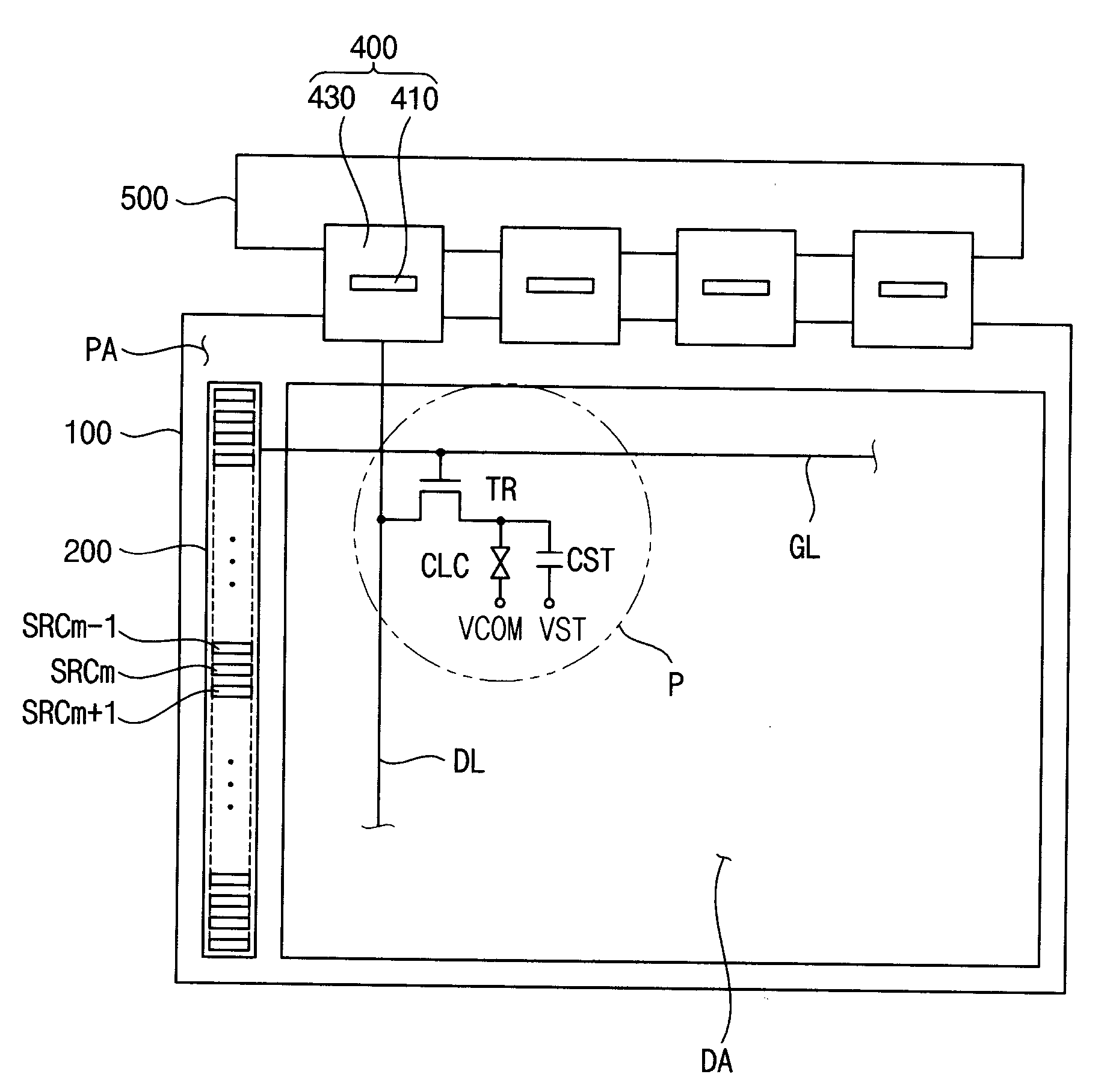
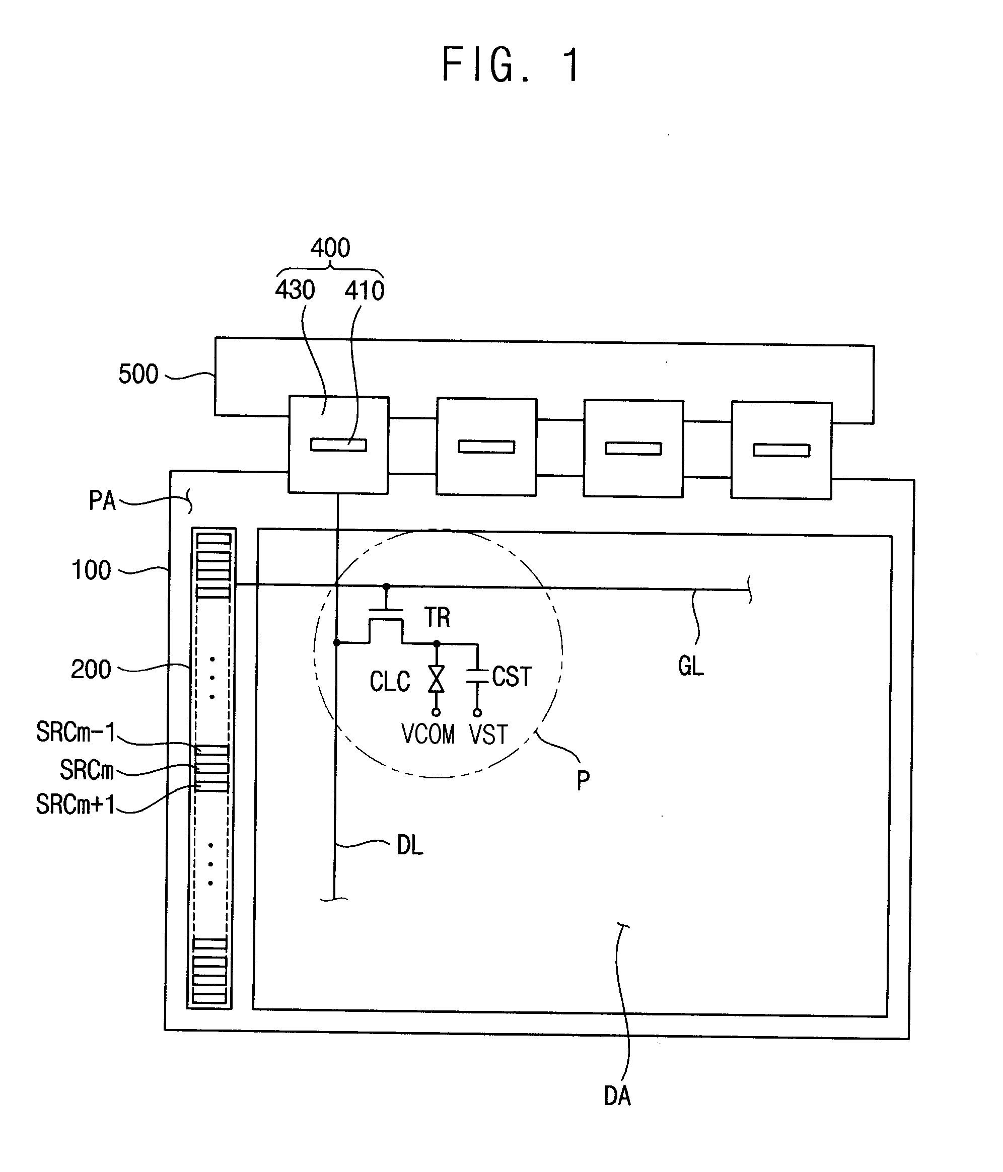
[0030]FIG. 1 is a plan view illustrating an exemplary display device according to Embodiment 1 of the present invention.

[0031]Referring to FIG. 1, the display device includes a display panel 100, a gate driving circuit 200, a source driving circuit 400 and a printed circuit board (PCB) 500.

[0032]The display panel 100 includes a display area DA and a peripheral area PA surrounding the display area DA. The display area DA includes a plurality of gate lines GL, a plurality of source lines DL, also known as data lines, and a plurality of pixel parts P. Each pixel part P includes a transistor TR electrically connected to the gate lines GL and the source lines DL, a liquid crystal capacitor CLC electrically connected to the transistor TR and a storage capacitor CST connected in parallel to the liquid crystal capacitor CLC. A common voltage VCOM is applied to a common electrode of the liquid crystal capacitor CLC, and a storage common voltage VST is applied to a common electrode of the sto...

example embodiment 2

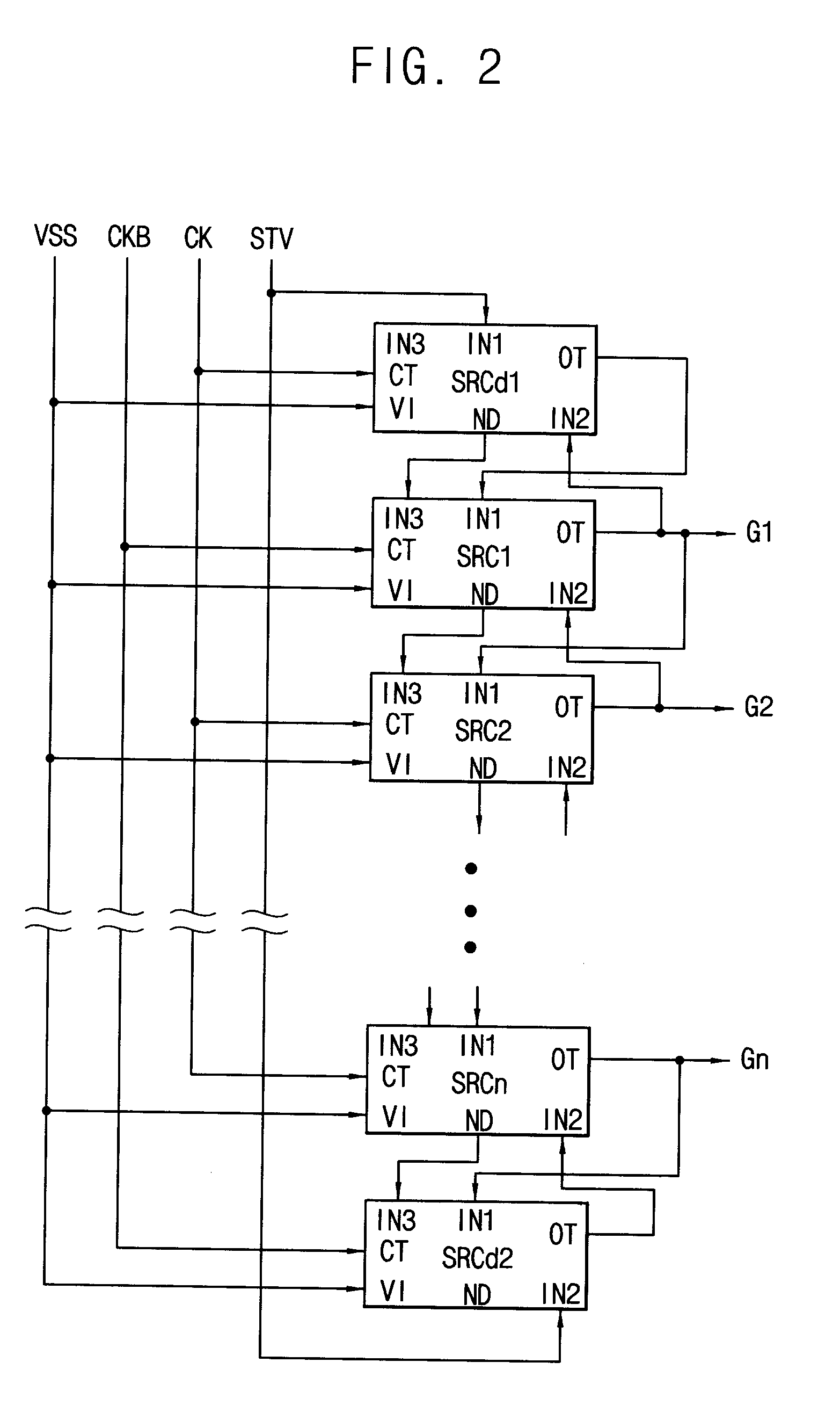
[0066]FIG. 7 is a block diagram illustrating an exemplary gate driving circuit according to Embodiment 2 of the present invention.

[0067]Referring to FIG. 7, the gate driving circuit includes the first stage SRC1 to the n-th stage SRCn dependently connected to each other and a shift register including the first dummy stage SRCd1 and the second dummy stage SRCd2.

[0068]The first stage SRC1 to the n-th stage SRCn are connected to n gate lines G1 to Gn, respectively, so that the stages sequentially output n gate signals to the gate lines. The first dummy stage SRCd1 controls the driving operation of the first stage SRC1, and the second dummy stage SRCd2 controls the driving operation of the n-th stage SRCn. The first dummy stage SRCd1 and the second dummy stage SRCd2 are not connected to the gate lines.

[0069]Each of the stages includes a clock terminal CT, a first input terminal IN1, a second input terminal IN2, a third input terminal IN3, a voltage terminal V1, a carry terminal CR, a no...


PUM


Abstract

An output part outputs a high voltage of a first clock signal as a high voltage of an (m)-th gate signal (‘m’ is a natural number) and a low voltage in response to a high signal of an (m+1)-th gate signal outputted from an (m+1)-th stage. A first maintenance part maintains a control part of the pull-up part at a low voltage in response to an (m−1)-th node signal or an (m+1)-th node signal lower than a high signal of a second clock signal having a phase opposite to the phase of the first clock signal received from an (m−1)-th stage or the (m+1)-th stage. A second maintenance part maintains the low voltage of the (m)-th gate signal in response to the (m−1)-th node signal or the (m+1)-th node signal.

Description

[0001]This application claims priority to Korean Patent Application No. 2008-107112, filed on Oct. 30, 2008, and all the benefits accruing therefrom under 35 U.S.C. §119, the contents of which in its entirety are herein incorporated by reference.BACKGROUND OF THE INVENTION[0002]1. Field of the Invention[0003]Exemplary embodiments relate to a gate driving circuit and a display device having the gate driving circuit. More particularly, exemplary embodiments relate to a gate driving circuit for improving the reliability of driving for a long time and a display device having the gate driving circuit.[0004]2. Description of the Related Art[0005]Recently, to reduce manufacturing costs and the total size of a panel module for a display device, an amorphous silicon gate (“ASG”) technology that includes simultaneously forming a gate driving circuit in a peripheral area of a panel, and a switching device disposed in a display area of a panel, has been applied.[0006]Since the ASG technology in...

Claims


Application Information

Patent Timeline
Patent Type & Authority Applications(United States)
IPC IPC(8): G06F3/038
CPCG09G3/3677G09G2310/0286G02F1/133G09G3/20G09G3/36
Inventor YOON, SOO-WANGOH, JOON-CHULCHAI, CHONG-CHULYOON, YOUNG-SOOJO, SEI-HYOUNG
Owner SAMSUNG DISPLAY CO LTD
Why Eureka
Try Eureka