Illumination device, light emitting element, and liquid crystal display device

a technology of light emitting elements and illumination devices, which is applied in the direction of illuminated signs, display means, instruments, etc., can solve the problems of high accuracy, inability to secure brightness uniformity, and increase the weight of illumination devices, so as to improve brightness of the whole light emitting surface, reduce the amount of direct light emitted, and improve brightness. uniform

Active Publication Date: 2010-05-06
SHARP KK
View PDF9 Cites 56 Cited by
  • Summary
  • Abstract
  • Description
  • Claims
  • Application Information

AI Technical Summary

Benefits of technology

[0039]Conventionally, the light sources have been provided so as to be in contact with edge surfaces of the light guiding body. With the arrangement described above, however, the light sources are provided inside the light guiding body, so that it becomes possible to provide the light sources even in the center of the light emitting surface. Thereby, it is possible to enhance brightness of the whole light emitting surface, even when the illumination device becomes larger. Further, by providing the light sources inside the light guiding body, it is possible to realize an illumination device which is thinner than an illumination device in which light sources are provided behind the light guiding body.
[0040]Furthermore, the light sources emit light from their side surfaces which face the side surfaces of the concave portions provided on the bottom surface of the light guiding body. This can reduce the amount of light directly emitted from the light emitting surface, so as to prevent the light source providing

Problems solved by technology

Further, when the light guiding bodies are provided to partially overlap each other, like the surface light source device disclosed in Patent Document 2, each overlapping of the light guiding bodies causes an increase in weight of the illumination device.
Furthermore, the arrangement i

Method used


Image

  • Illumination device, light emitting element, and liquid crystal display device
  • Illumination device, light emitting element, and liquid crystal display device
  • Illumination device, light emitting element, and liquid crystal display device

Examples


Embodiment Construction

[0088]One embodiment of the present invention is described in detail below with use of examples, and with reference to the attached drawings. Note that sizes, materials, shapes, relative locations, and the like, of constituents described in the embodiment are merely examples for explanations, and therefore do not limit the scope of the present invention, as long as they are not particularly specified.

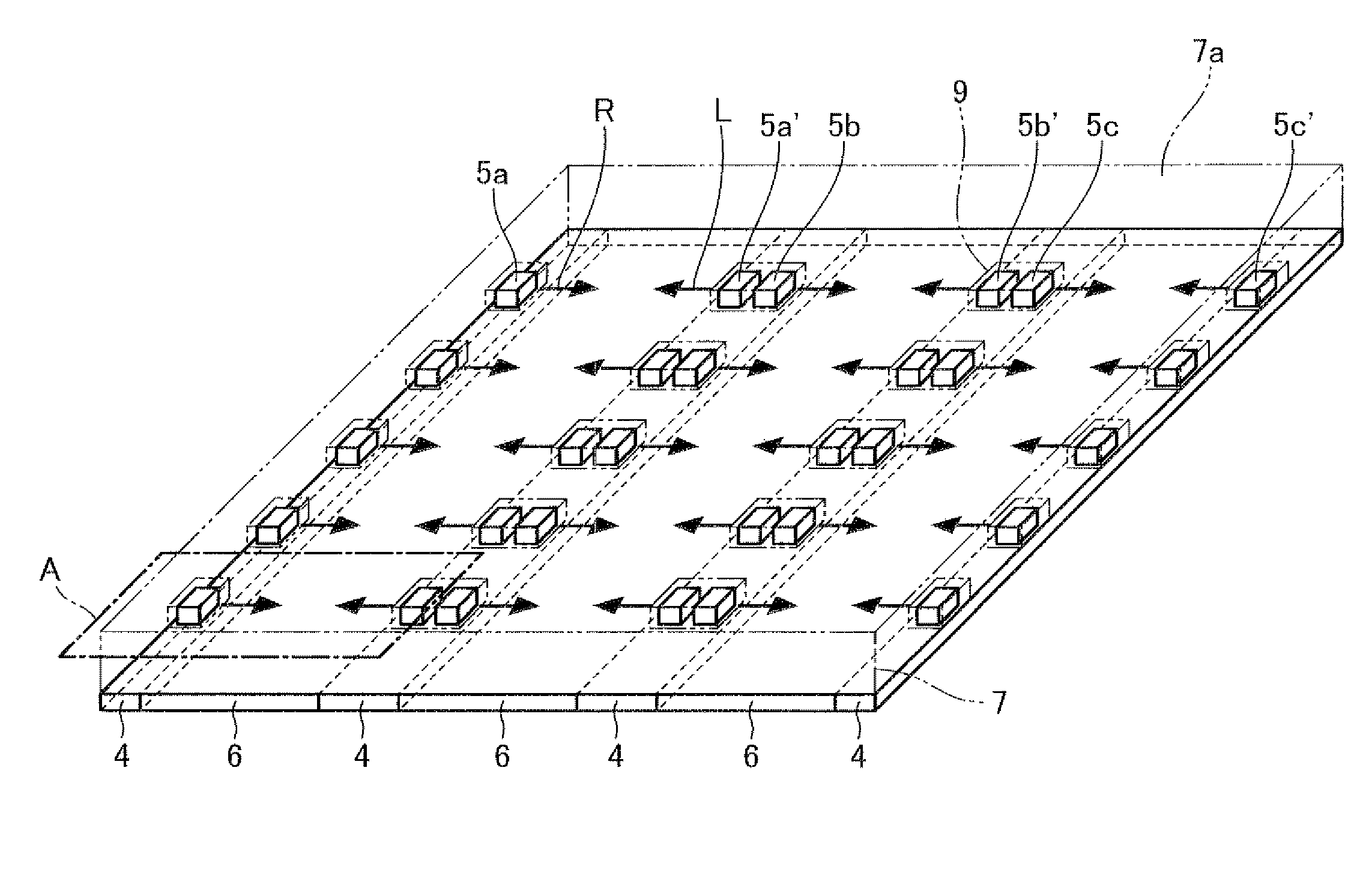
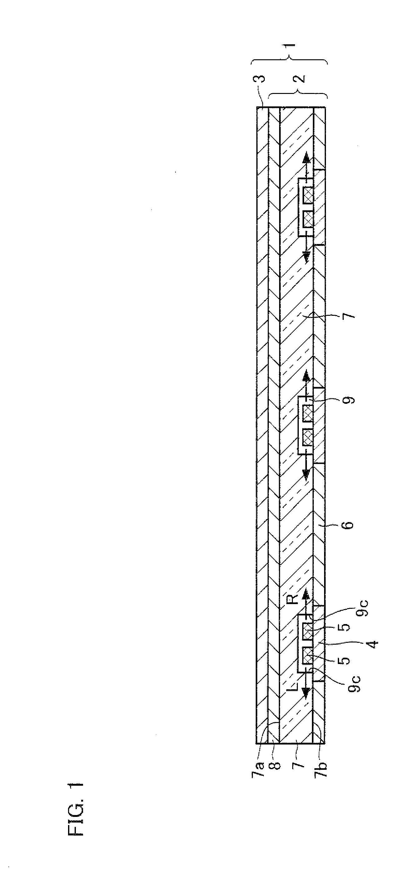
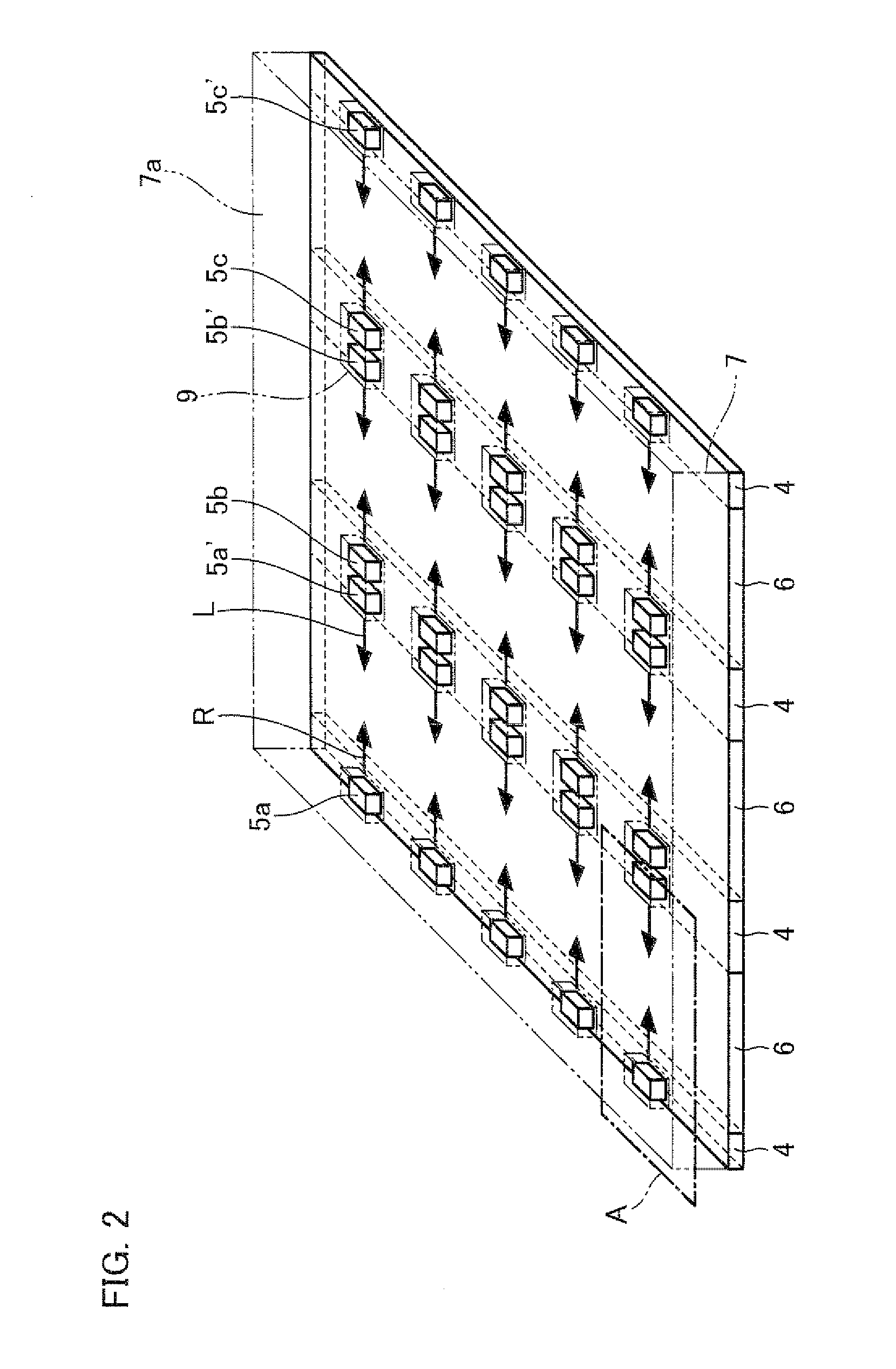
[0089]In the present embodiment, an illumination device used as a backlight of a liquid crystal display device is explained with reference to FIGS. 1 through 11.

[0090]FIG. 1 illustrates a liquid crystal display device 1 in accordance with the present embodiment. The liquid crystal display device 1 includes a backlight 2 (illumination device) and a liquid crystal display panel 3. A description regarding an arrangement of the liquid crystal display panel 3 is omitted because it has the same arrangement as a general liquid crystal display panel used in a conventional liquid crystal display...


PUM


Abstract

A backlight (illumination device) according to the present invention includes a plurality of light sources, and a light guiding body for causing light emitted from the light sources to be emitted from a light emitting surface. The light sources are provided inside the light guiding body, and emit light in directions which are substantially parallel to a light emitting surface of the light guiding body. At least two of the plurality of light sources emit the light in directions which are different from each other. More specifically, at least two of the plurality of light sources are provided so as to face each other, and provided so that one of the plurality of light sources emits light toward the other one of the plurality of light sources, and vice versa.

Description

TECHNICAL FIELD[0001]The present invention relates to an illumination device used as a backlight of a liquid crystal display device, and to a liquid crystal display device including the illumination device.BACKGROUND ART[0002]Liquid crystal display devices have become rapidly popular in place of cathode ray tube (CRT) based display devices in recent years. The liquid crystal display devices have been in widespread use in liquid crystal televisions, monitors, mobile phones, and the like, which take advantage of energy saving, thin, lightweight features and other features of the liquid crystal display devices. One of ways to further take advantage of such features is to improve an illumination device (i.e. a backlight) which is provided behind a liquid crystal display device.[0003]The illumination devices are roughly classified into a side light type (an edge light type) and a direct type. A side light illumination device is arranged so that a light guiding body is provided behind a l...

Claims


Application Information

Patent Timeline
IPC IPC(8): G02F1/1335G02F1/13357
CPCG02B6/0021G02B6/0046G02B6/0068G02B6/0078G02F1/133603G02F1/133611
Inventor AJICHI, YUHSAKUMASUDA, TAKESHI
Owner SHARP KK
Why Eureka
Try Eureka