Storage Apparatus and Method of Managing Data Storage Area

a storage apparatus and data technology, applied in the direction of memory address/allocation/relocation, instruments, computing, etc., can solve the problems of increasing the substitution frequency of ssd, increasing the expected rapid wear of mlc, so as to reduce the cost of bit, the effect of prolonging the service life of the storage apparatus

Active Publication Date: 2010-05-06
HITACHI LTD
View PDF1 Cites 49 Cited by
  • Summary
  • Abstract
  • Description
  • Claims
  • Application Information

AI Technical Summary

Benefits of technology

[0015]According to the embodiment of the invention, in a storage apparatus having a plurality of types of sto

Problems solved by technology

For this reason, when the rewrite frequency of data stored in the MLC becomes high, the MLC is expected to be rapidly worn out.
The decrease in the endurance of the SSD causes an increase in substitution frequency of the SSD, and as a result, bit cost increases.
When the rewrite frequency of data stored in the SLC becomes l

Method used


Image

  • Storage Apparatus and Method of Managing Data Storage Area
  • Storage Apparatus and Method of Managing Data Storage Area
  • Storage Apparatus and Method of Managing Data Storage Area

Examples


first embodiment

[0032]A first embodiment will now be described with reference to FIGS. 1 to 6.

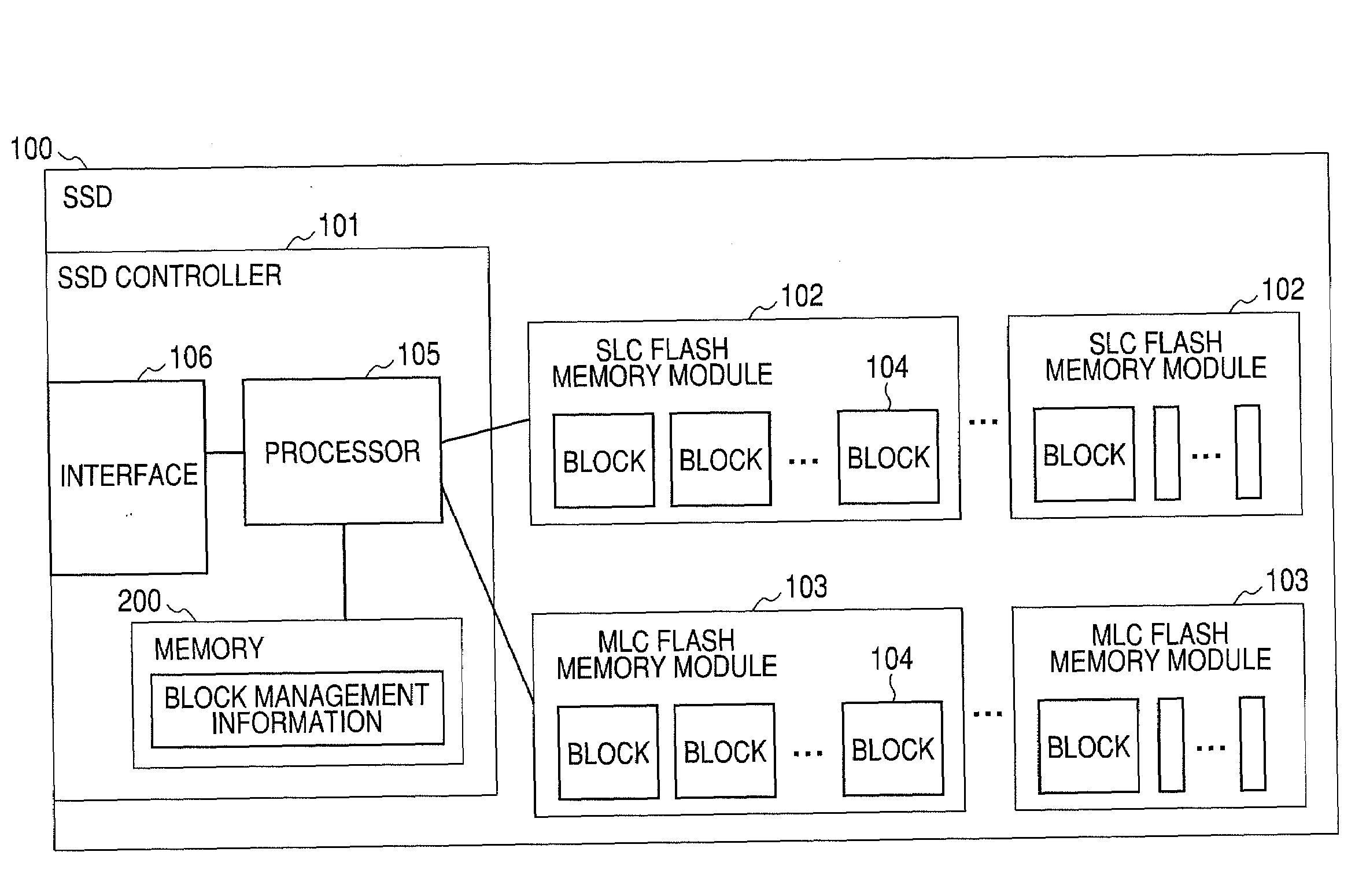
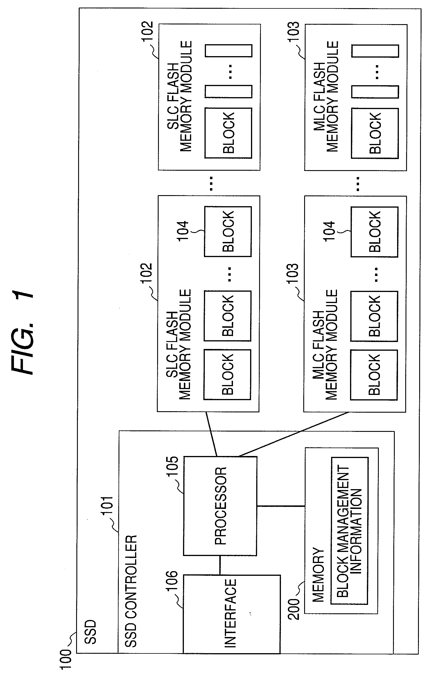
[0033]FIG. 1 is a block diagram showing an example of an SSD 100 as a storage apparatus using a flash memory according to the first embodiment of the invention.

[0034]The SSD 100 includes an SSD controller 101, an SLC flash memory module 102, and an MLC flash memory module 103.

[0035]The SSD controller 101 controls the entire SSD 100. The SSD controller 101 has a processor 105, an interface 106, and block management information 200. The processor 105 controls data input / output. The interface 106 receives a data input / output request. The block management information 200 stores information for managing blocks 104.

[0036]The SLC flash memory module 102 and the MLC flash memory module 103 are coupled to the SSD controller 101. The flash memory module is a memory module in which a plurality of flash memory chips are mounted on a printed board. The flash memory module has a plurality of blocks 104 that store data t...

second embodiment

[0083]According to the first embodiment of the invention, the invention is applied to the SSD including the SSD controller, but according to a second embodiment, the invention is applied to a storage system having mounted thereon a plurality of flash memory modules. In the second embodiment, instead of the SSD controller, a storage controller controls data input / output with respect to the flash memory modules.

[0084]Hereinafter, the second embodiment will be described with reference to FIGS. 7 to 10. In the second embodiment, the same contents as the first embodiment will be appropriately omitted.

[0085]FIG. 7 is a block diagram showing an example of the configuration of a computer system according to the second embodiment of the invention.

[0086]The computer system according to the second embodiment of the invention includes a storage system 400, a host computer 401, and a management server 402.

[0087]The storage system 400 stores data to be read and written by the host computer 401. T...

third embodiment

[0125]According to the second embodiment of the invention, the invention is applied to the storage system having flash memory packages, but according to a third embodiment, the invention is applied to a storage system having mounted thereon SSDs, not flash memory package. In the third embodiment, a storage controller controls SSDs.

[0126]Hereinafter, the third embodiment will be described with reference to FIGS. 11 to 14. In the third embodiment, the same contents as the first embodiment or the second embodiment will be appropriately omitted.

[0127]FIG. 11 is a block diagram showing an example of the configuration of a computer system according to the third embodiment of the invention.

[0128]Similarly to the second embodiment, the computer system according to the third embodiment of the invention includes a storage system 400, a host computer 401, and a management server 402. The third embodiment has the storage system 400 different from the second embodiment.

[0129]The storage system 4...


PUM


Abstract

Disclosed is a storage apparatus that extends endurance and reduces bit cost. A storage apparatus includes a controller and a semiconductor storage media that has a plurality of storage devices. The plurality of storage devices include a first storage device and a second storage device having an upper limit of an erase count of data smaller than that of the first storage device. Area conversion information includes correspondence of a first address to be specified as a data storage destination and a second address of an area in which data is to be stored. A rewrite frequency of stored data is recorded for each area. The controller selects an area corresponding to the first address, determines whether or not the rewrite frequency of the selected area is equal to or larger than a first threshold value, when the rewrite frequency is equal to or larger than the threshold value, selects an area to be provided by the first storage device, and when the rewrite frequency is smaller than the threshold value, selects an area to be provided by the second storage device and maps the address of the selected area to the first address.

Description

CROSS REFERENCES TO RELATED APPLICATIONS[0001]This application relates to and claims priority from Japanese Patent Application No. 2008-279661, filed on Oct. 30, 2008, the entire disclosure of which is incorporated herein by reference.BACKGROUND OF THE INVENTION[0002]1. Field of the Invention[0003]The present invention relates to a storage apparatus having a semiconductor storage media, and in particular, to a technology for managing a data storage area.[0004]2. Description of the Related Art[0005]In recent years, a nonvolatile semiconductor memory, such as a flash memory, which supports high-speed access, is attracting attention. A flash memory which has come into wide use is called a NAND flash memory, and is divided into MLC (Multiple Level Cell) and SLC (Single Level Cell) according to the characteristic of the storage device. The MLC has a storage capacity of two or more bits per memory cell, and has features of low bit cost, low performance, and short endurance. The SLC has a ...

Claims


Application Information

Patent Timeline
IPC IPC(8): G06F12/12G06F12/06
CPCG06F12/0246G06F2212/1036G06F2212/7202G06F2212/7211G11C2211/5641
Inventor ARAKI, AKIHIKOKANO, YOSHIKISUGIMOTO, SADAHIRONONAKA, YUSUKE
Owner HITACHI LTD
Why Eureka
Try Eureka