Method of joining pieces of metal material and a welding device

a welding device and metal material technology, applied in the field of joining pieces of metal material and a welding device, can solve the problems of insufficient melt, small size, and inability to form grooves or gaps in the upper part of said t, and achieve the effect of reducing the need for post-treatment of the weld area

Inactive Publication Date: 2010-05-13
VOLVO AERO CORP
View PDF9 Cites 5 Cited by
  • Summary
  • Abstract
  • Description
  • Claims
  • Application Information

AI Technical Summary

Benefits of technology

[0015]According to one embodiment said beam-reflecting side element is removably arranged at said surface. Thereby, the need of post-treatment of the weld area may be reduced. Alternatively said beam-reflecting side element is removably attached to said surface.
[0016]According to yet another one embodiment said beam-reflecting element is separate from said surface. Thereby, unwanted interaction between the beam-reflecting element and the piece of material to be welded may be prevented.

Problems solved by technology

Thereby, the energy remaining for the generation of a melt in the material to be welded becomes to small, and, accordingly, the melt will be insufficient for a well-defined and proper weld joint to be generated.
However, when, for example, a T-joint is to be generated by the application of a laser beam onto an through the upper part of said T, the formation of such a groove or gap in the upper part of said T might not be a favourable solution, from both technical and economical reasons.

Method used


Image

  • Method of joining pieces of metal material and a welding device
  • Method of joining pieces of metal material and a welding device
  • Method of joining pieces of metal material and a welding device

Examples


Embodiment Construction

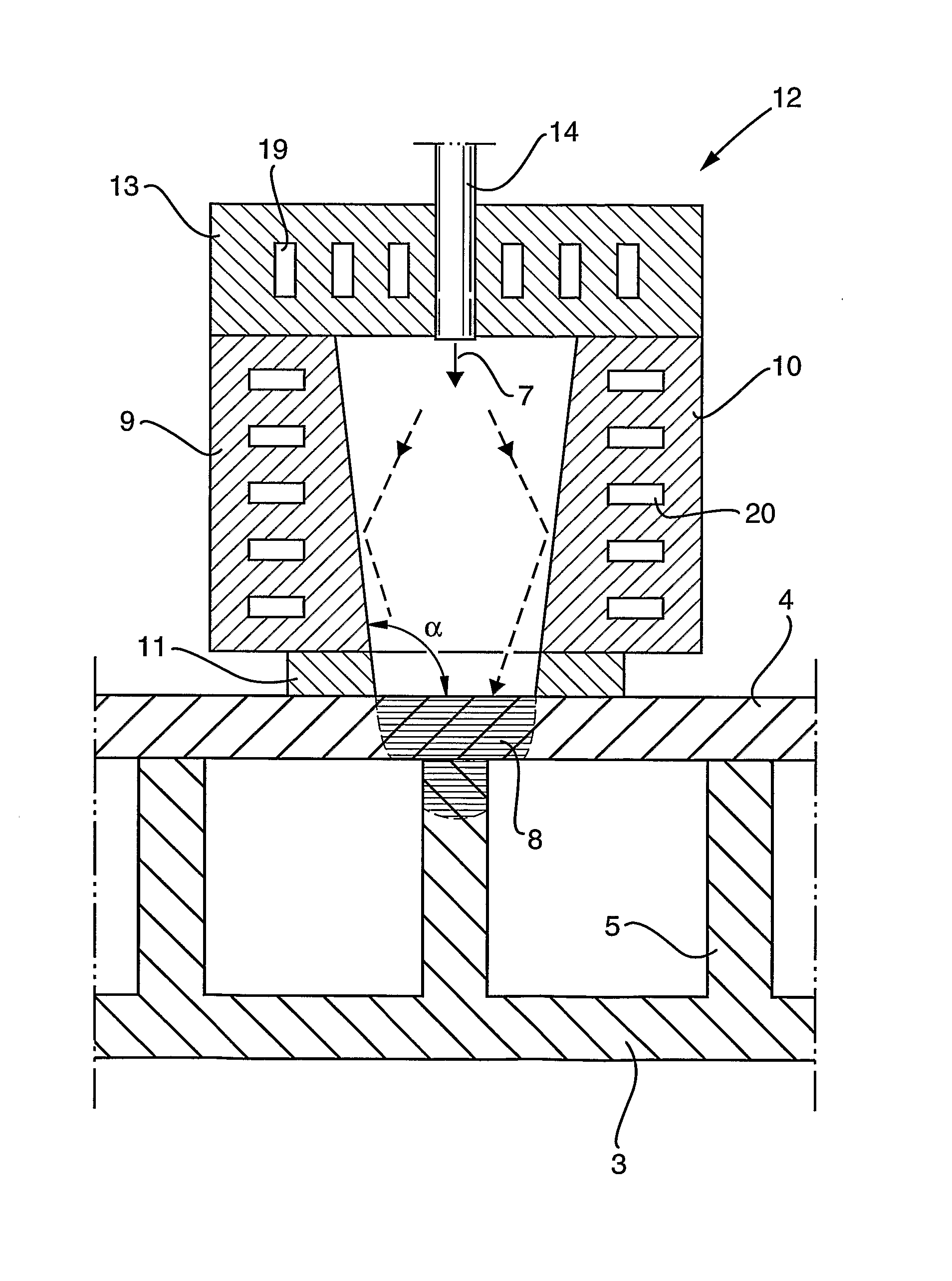
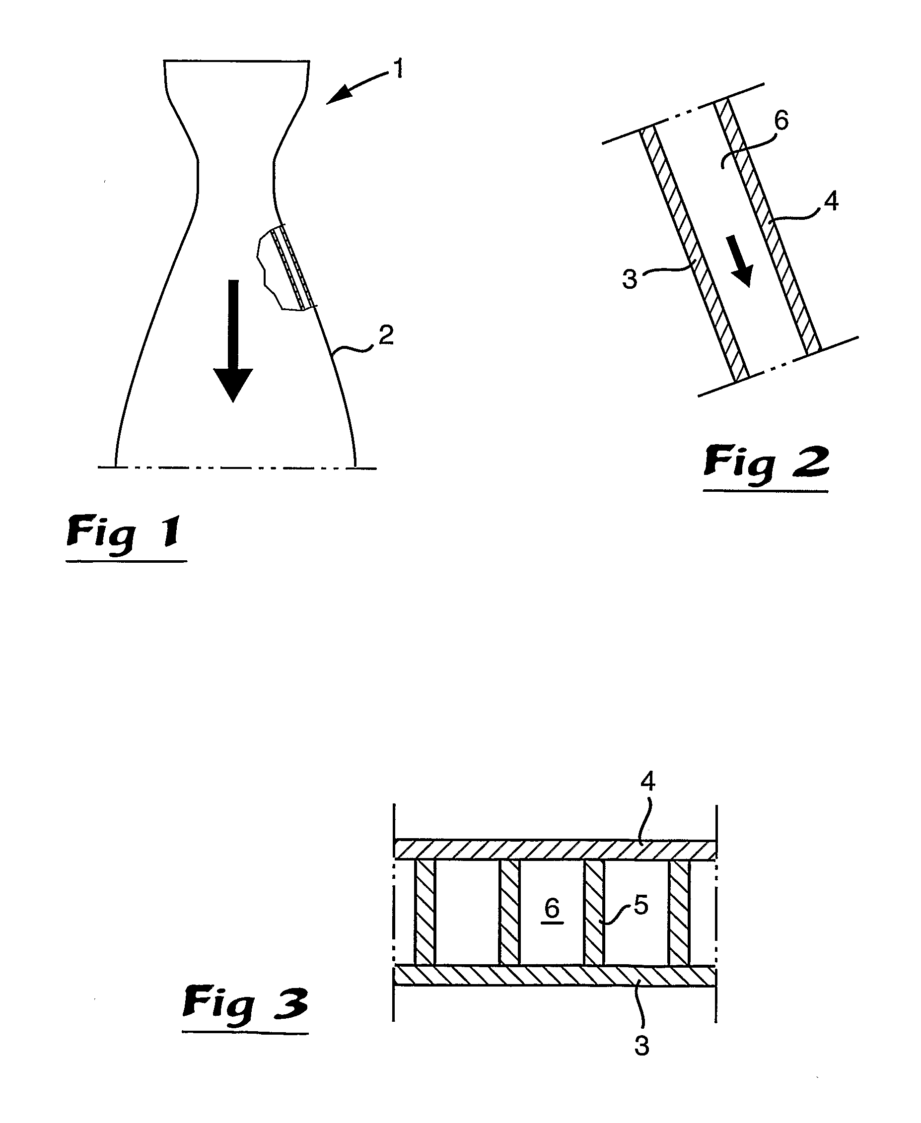
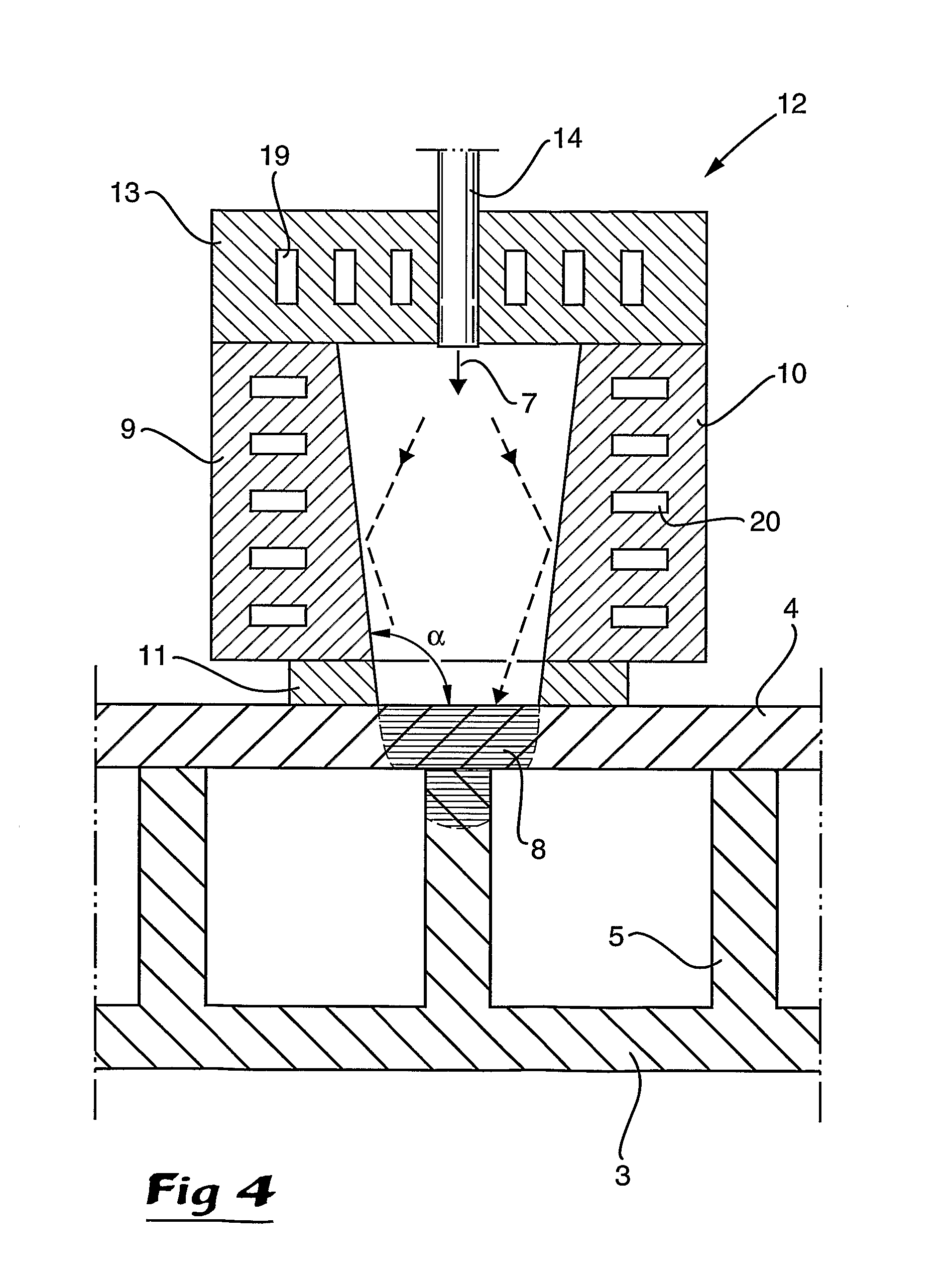
[0045]FIGS. 1 and 2 are schematic representations of the thrust nozzle 1 of a rocket engine. The nozzle 1 comprises and is defined by a generally cone-shaped engine wall 2. The engine wall 2 is provided with an inner wall 3, preferably with a thickness of 0.15-2 mm, and an outer wall 4, interconnected by a plurality of webs 5, as shown in FIG. 3. In the space between the inner wall 3 and the outer wall 4 there are ducts 6 that are used for cooling purposes, each duct 6 being delimited by two adjacent webs 5, the inner wall 3 and the outer wall 4. During operation of the engine a cooling medium, preferably the fuel or part of the fuel of the engine, is permitted to flow through the ducts 6 for the purpose of cooling the engine wall 2. This technique applies to satellite launchers and space planes, and also in satellite thrusters, nuclear reactors and high efficiency boilers, and it can also be applied to heat shields or to the nose cones of vehicles travelling at very high speed.

[004...


PUM

PropertyMeasurementUnit
angleaaaaaaaaaa
angleaaaaaaaaaa
obtuse angleaaaaaaaaaa

Abstract

A welding device includes at least one beam-reflecting side element arranged so as to reflect at least a part of a high energy density beam towards a region in which a weld joint is to be generated in a piece of material, wherein the beam-reflecting side element protrudes from a surface of said piece of material.

Description

BACKGROUND AND SUMMARY[0001]The present invention relates to a method of joining pieces of metal material by means of high energy density welding, comprising directing a high energy density beam to a surface of a piece of material into which a weld joint is to be generated.[0002]The invention also relates to a welding device for the implementation of the method according to the invention.[0003]In particular, the invention primarily relates to applications by which, by means of said weld joint, said piece of material is joined to a second piece of material provided on an opposite side of the first piece of material in relation to the surface thereof towards which said high energy density beam is directed.[0004]Typically, the first piece of material is a sheet and that the second piece of material is a transverse element, the joint to be formed between said pieces of material being a T-joint. Preferably, said first piece of material is a first wall element of an engine wall, and said ...

Claims


Application Information

Patent Timeline
Patent Type & Authority Applications(United States)
IPC IPC(8): B23K15/00B23K26/00
CPCB23K26/0643B23K26/0665B23K26/123B23K26/064B23K26/1224
Inventor BOMAN, ARNE
Owner VOLVO AERO CORP
Why Eureka
Try Eureka