
Permanent Magnet Machine with Offset Pole Spacing

a permanent magnet machine and offset pole technology, applied in battery/cell propulsion, engine-driven generator propulsion, transportation and packaging, etc., can solve the problems of adversely affecting the operation efficiency of the motor, and achieve the effect of reducing the amplitude of the total ripple of the machin

Inactive Publication Date: 2010-05-13
FORD GLOBAL TECH LLC
View PDF25 Cites 40 Cited by
  • Summary
  • Abstract
  • Description
  • Claims
  • Application Information

AI Technical Summary

Benefits of technology

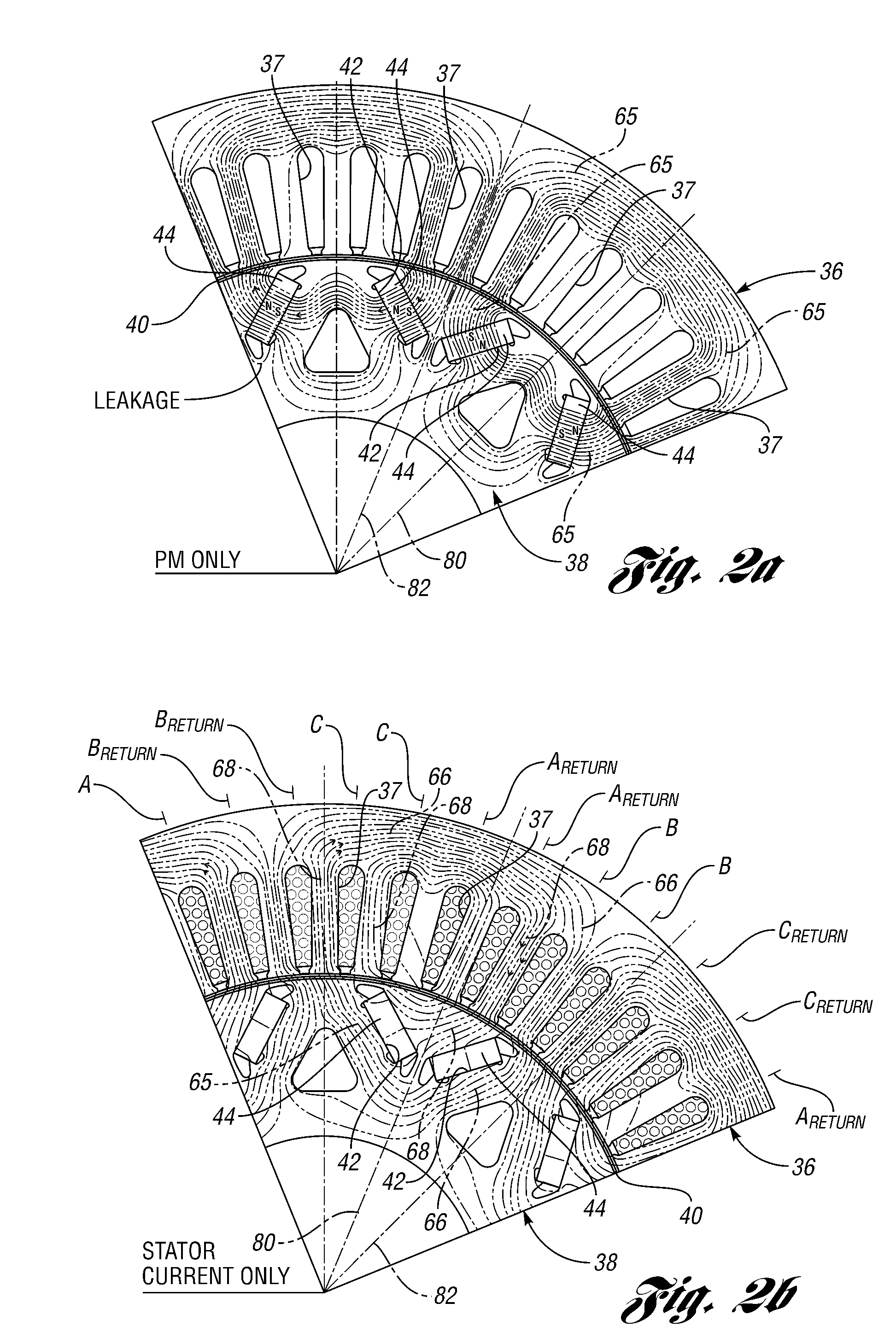
[0007]An objective of the invention is to minimize a so-called torque ripple with minimal reduction in average torque. This differs from the invention of copending application Ser. No. 11 / 839,928, filed Aug. 16, 2007 entitled “Permanent Magnet Machine,” which is assigned to the assignee of the invention, in which an objective is to improve motor efficiency during operation in a motoring mode by using asymmetry in rotor design features of the motor while allowing an acceptable decrease in regenerative energy recovery during operation in a generating mode.
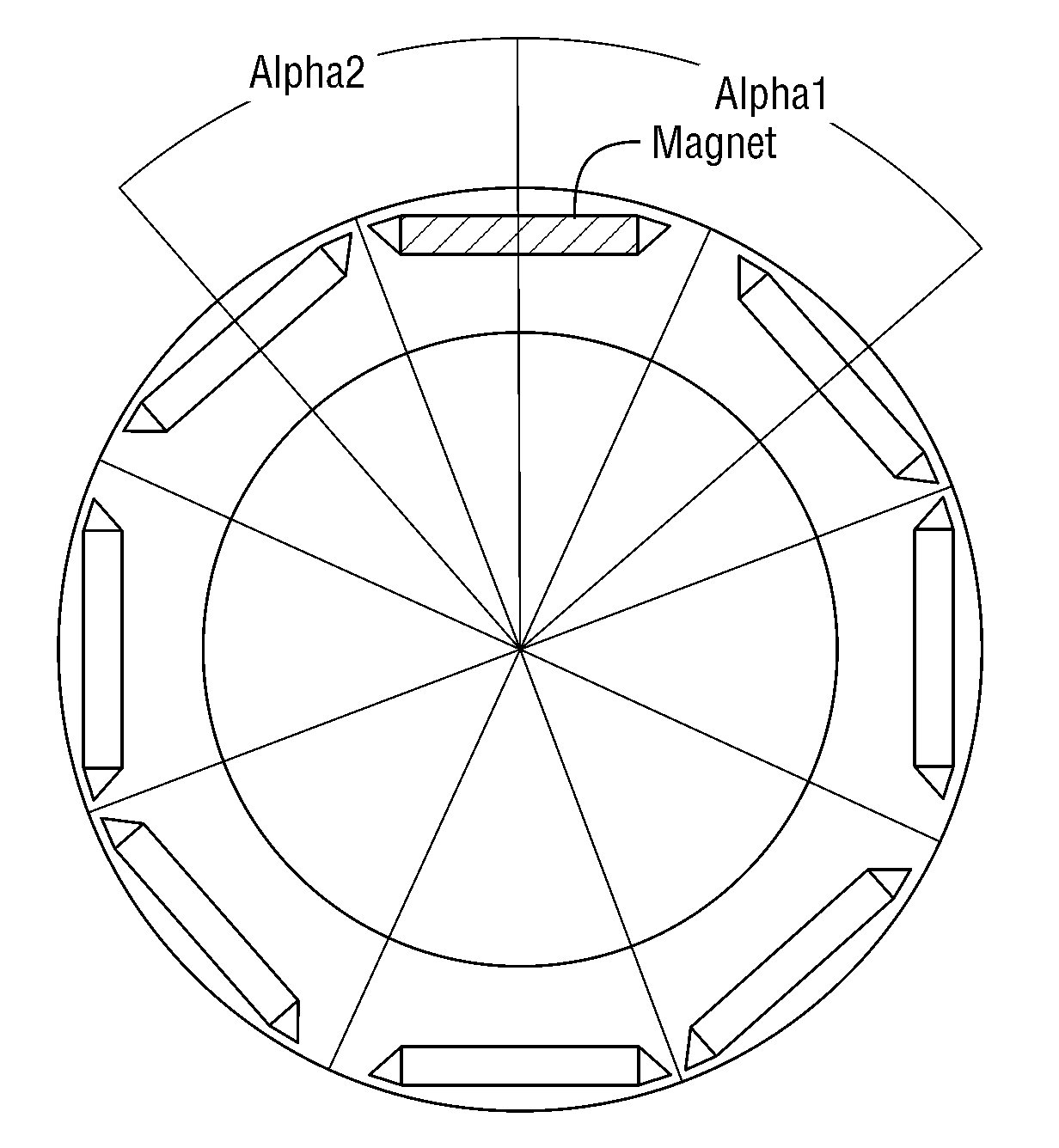
[0008]The present invention will break the symmetry of the rotor laminations, so that at a given instant the torque contributions of the multiple sections will be altered to reduce torque ripple.
[0010]In a second embodiment of the invention, the rotor magnets are arranged in a “V” configuration. The shape of the torque ripple is a function of the shape of the “V” configuration. By using at least two different, properly designed “V” configurations in the laminations, the total machine ripple can be reduced in amplitude.

Problems solved by technology

This is manifested by a motor torque ripple, or torque oscillation, accompanied by vibration and noise.
Further, operating efficiency of the motor is affected adversely.

Method used


Image

  • Permanent Magnet Machine with Offset Pole Spacing
  • Permanent Magnet Machine with Offset Pole Spacing
  • Permanent Magnet Machine with Offset Pole Spacing

Examples


first embodiment

[0058]the invention is shown in FIG. 5, where a rotor lamination has poles that are radially skewed. The skewing is realized within each lamination itself by offsetting the magnetic axis of a motor pole with respect to an adjacent pole.

[0059]Manufacture of the rotor is simplified by the absence of several steps usually needed to create multiple, axially-stacked rotor sections. This manufacturing method is especially valuable in the case of an integrated starter-generator type motor, where the stacked length of the sections is normally short and the known skewing method described with reference to FIG. 3 is not feasible. The embodiment of the invention, however, is not limited to short stack motors and generators, but it can be applied to any permanent magnet machine. It can exceed the performance of an electric machine with known skewing and it may be made using simpler manufacturing processes. The performance improvement is due to a further reduction of the torque ripple previously...

third embodiment

[0071]the invention makes it possible to form the laminations of multiple axial sections in a manufacturing process using a single rotor lamination stamping die in order to avoid multiple lamination types in the same rotor.

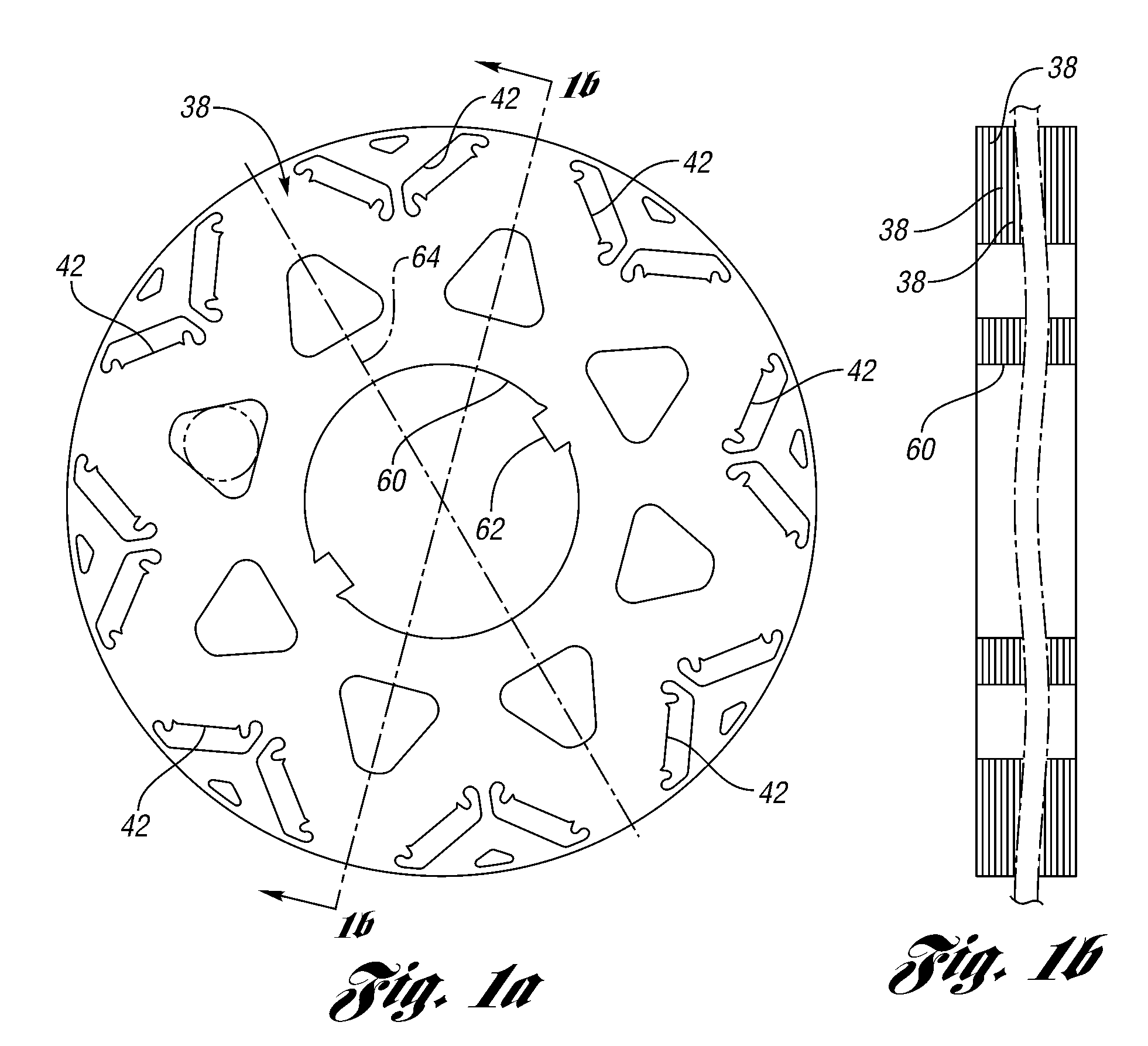
[0072]FIG. 14 shows a known skewing arrangement for a permanent magnet motor using a single lamination type where the first section of the rotor is assembled by stacking half of the rotor laminations and inserting the magnets in their magnet openings. The laminations have a key slot 124, where key slot axis 130 is rotated with respect to the nearest pole axis 126 by a certain angle. To create the second section of the rotor, the rest of the laminations are flipped around axis 130, as shown in FIGS. 14 and 15. Because of the flip, the pole axis shown at 126 in FIG. 14 becomes pole axis 128 in FIG. 15 and is rotated by Gamma with respect to axis 130 in the counter-clockwise direction. The optimum angle would be determined based on the harmonic content of the air gap...


PUM


Abstract

An internal permanent magnet machine has multiple rotor sections, each section having multiple rotor laminations. Permanent magnets are placed asymmetrically in lamination openings to attenuate oscillations in torque caused by harmonic components of magnetic flux.

Description

BACKGROUND OF THE INVENTION[0001]1. Field of the Invention[0002]The invention relates to an inner permanent magnet machine having a rotor with multiple laminations in axially stacked relationship.[0003]2. Background Art[0004]An inner permanent magnet machine typically includes a stator with stator coil windings and a rotor with circumferentially spaced permanent magnets on the rotor periphery that cooperate with circumferentially spaced stator poles separated from the periphery of the rotor with a calibrated air gap. When the machine is acting as a motor, the coils are energized by an electrical current to effect rotation of the rotor. The current has an alternating waveform, typically of sinusoidal shape, which creates an electromotive rotor torque. The interaction of an electromagnetic flux flow path created by the stator windings with the flux flow path created by the permanent magnets typically is accompanied by harmonic waveform components that induce motor torque fluctuations....

Claims


Application Information

Patent Timeline
IPC IPC(8): H02K21/14
CPCH02K1/2766Y02T10/641H02K2201/06B60L11/14B60L15/2009B60L2210/10B60L2210/30B60L2210/40B60L2240/12B60L2240/421B60L2240/423B60L2270/142B60L2270/145B60L7/14B60L11/123Y02T10/7077Y02T10/7241Y02T10/7275Y02T10/7216Y02T10/6217Y02T10/642H02K29/03H02K1/2753B60L50/16B60L50/61Y02T10/62Y02T10/64Y02T10/70Y02T10/7072Y02T10/72H02K1/274H02K1/278H02K15/03H02K21/16
Inventor LEONARDI, FRANCODEGNER, MICHAEL W.LIANG, FENG
Owner FORD GLOBAL TECH LLC
Learn More