Acoustic condition sensor employing a plurality 0f mutually non-orthogonal waves

Inactive Publication Date: 2010-05-13
ELO TOUCH SOLUTIONS INC
View PDF26 Cites 166 Cited by
  • Summary
  • Abstract
  • Description
  • Claims
  • Application Information

AI Technical Summary

Benefits of technology

[0105](f) Ability to reliably reconstruct multiple touches and hence support applications

Problems solved by technology

The applicability of such systems as commonly employed is restricted by the following major limitations.
First, acoustically absorptive contamination in localized regions, e.g. a water drop on a known Rayleigh-wave sensor, result in large areas of shadowing in which two-dimensional touch positions cannot be reconstructed.
Second, the configurational requirements of these sensors limits their versatility with regard to shape and size.
Third, reconstruction of touch coordinates may lead to ambiguities when more than one touch is applied simultaneously.
Finally, such sensors provide limited touch characteristic information from which to differentiate valid touches from false touches, e.g. fingers from water drops.
In contrast, few if any touchscreen products are presently available for applications in which the touchscreen is an input device that is intended to be used by more than one user simultaneously.
However, the basic principles of acoustic touchscreen operation are largely independent of the choice of acoustic mode.
Thus, users coming out of the rain or snow with wet clothes, gloves or umbrellas are likely to leave occasional drops of water on the touchscreen surface.
However, a cover sheet generally reduce

Method used


Image

  • Acoustic condition sensor employing a plurality 0f mutually non-orthogonal waves
  • Acoustic condition sensor employing a plurality 0f mutually non-orthogonal waves
  • Acoustic condition sensor employing a plurality 0f mutually non-orthogonal waves

Examples


example 1

[0368]FIG. 10 represents a generic sensor subsystem including transmit and receive transducers and arrays. This generic sensor subsystem includes a family of embodiments which differ in the various parameters.

[0369]Later examples will generalize to families of embodiments in which the acoustic path between the transmit and receive arrays are scattered one or more times by reflective boundaries. Later examples will also generalize to families of embodiments in which the sensor surface has non-planar geometry. In this example, we consider the generic sensor subsystem of FIG. 10.

[0370]In the embodiment of FIG. 10, a set of acoustic paths is associated with a sensor subsystem. Each member of the set of acoustic paths can be represented by a value between zero and one of a path parameter “s”. (In cases where a range other than zero to one is mathematically convenient; this can easily be accommodated with a change of variables.) The acoustic path for a given path parameter starts at the t...

example 2

[0380]FIG. 12 illustrates examples of specific touch region geometries within the scope of FIG. 10.

[0381]The rectangular touch region shown in FIG. 12(a) is typical of the X-coordinate sensor subsystems of current flat rectangular acoustic touchscreen products.

[0382]If all segments of the acoustic path in FIG. 12(a) use the same acoustic mode, then the spacing-vector formula leads to the prior art 45° reflectors with wavelength spacing along the array axes. For example, if the incident wave is in the −X direction and the scattered wave is in the Y direction, then the spacing vector is calculated to be S=(nλ / 2,nλ / 2) and hence the reflectors are at 45° the spacing between reflectors in a direction perpendicular to the reflectors is nλ / √2 and the reflector spacing in along the array axis nλ.

[0383]If, instead, the transmit and receive array modes are zeroth order horizontally polarized shear (ZOHPS) waves and the touch region mode is a Lamb wave, then the spacing vector is calculated to...

example 3

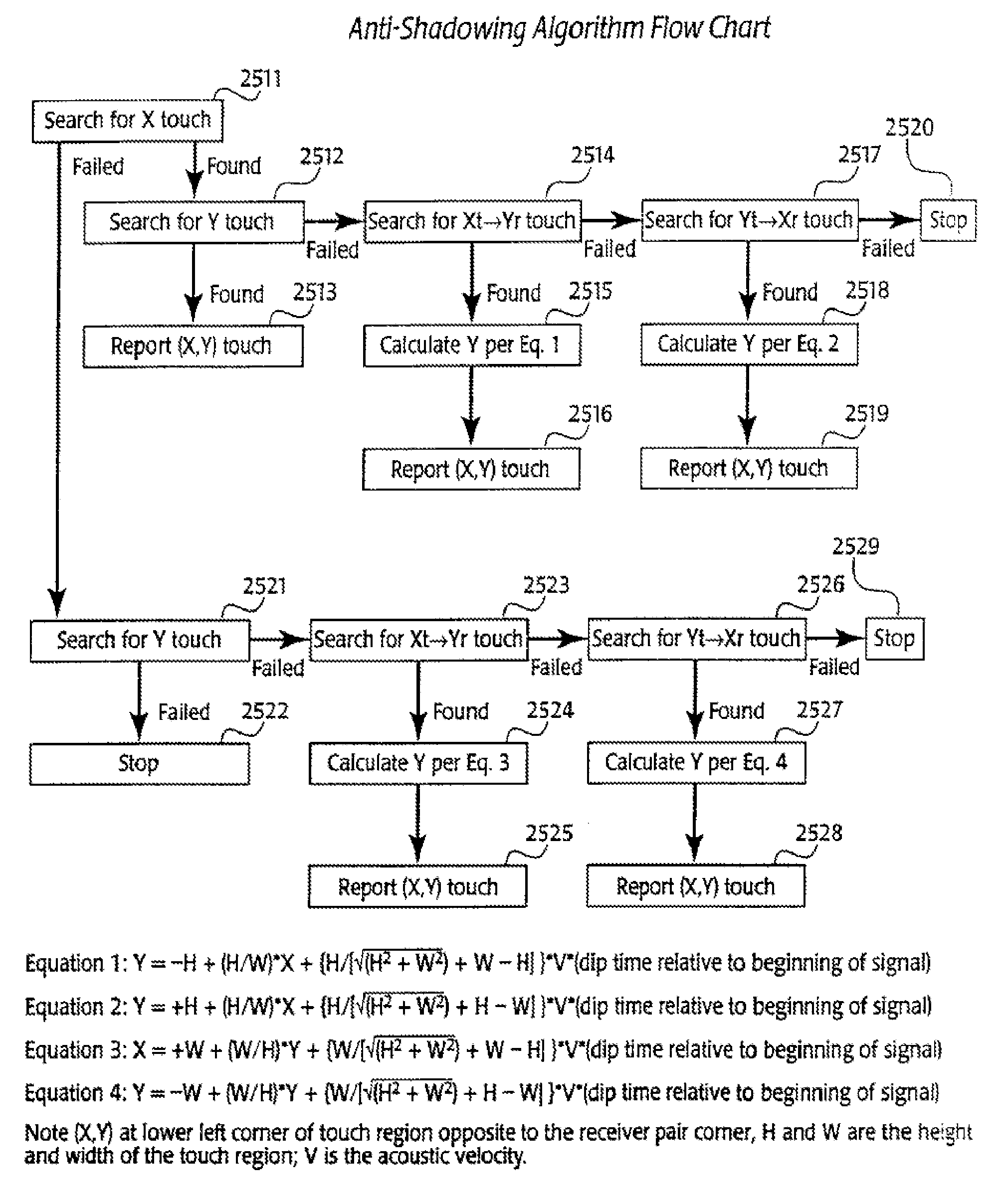
[0385]FIG. 13 represents an example sensor design that utilizes four sensor subsystems. This design supports control systems which include anti-shadowing algorithms and algorithms that resolve multi-touch ambiguities. The touch region has a width-to-height aspect ratio of √3:1.

[0386]Two sensor subsystems are rectangular as in FIG. 12(a); see FIG. 13(a). By itself, FIG. 13(a) has much in common with prior art sensors with standard X and Y measurements. FIG. 13(a) shows an X transmit transducer 1301, an X transmit reflective array 1302, with reflective elements at 45°, an X receive reflective array 1303, with reflective elements at 45°, and an X receive transducer 1304. Likewise, a Y transmit transducer 1305, a Y transmit reflective array 1306, with reflective elements at 45°, a Y receive reflective array 1307, with reflective elements at 45°, and a Y receive transducer 1308 is provided along an orthogonal set of axes.

[0387]The other two subsystems provide a measurement of a “U” diago...


PUM


Abstract

A touch input system, comprising a surface, adapted to receive at least one simultaneous touch inputs from human fingers; a sensor adapted to detect the at least one touch inputs and produce at least one signal representing a unique position for the at least one touch input; and a processor, adapted to receive the at least one signal and produce an output representing a touch detection and a mapping of a coordinate position on the surface for each of the simultaneous touch inputs. The system may detect, for example, two touch inputs simultaneously. The surface may be non-planar and distinct from a small solid angle section of a sphere.

Description

CONTINUING DATA[0001]The present application is a Continuation of U.S. patent application Ser. No. 11 / 336,694, filed on Jan. 20, 2006 (pending), which is a Continuation of U.S. patent application Ser. No. 10 / 827,847 filed on Apr. 20, 2004, now U.S. Pat. No. 7,061,475, which is a Continuation of U.S. patent application Ser. No. 10 / 178,692 filed on Jun. 22, 2002, now U.S. Pat. No. 6,723,929, which is a Divisional of U.S. patent application Ser. No. 09 / 220,302 filed on Dec. 23, 1998, now U.S. Pat. No. 5,986,224, which is a Divisional of U.S. patent application Ser. No. 08 / 695,716 filed on Aug. 12, 1996, now U.S. Pat. No. 5,854,450, each of which is expressly incorporated herein by reference.TECHNICAL FIELD OF THE INVENTION[0002]The present invention relates to an acoustic touch position sensor, and more particularly to such a sensor wherein a coordinate position, and optionally an absorption characteristic, of an acoustic disturbance is determined by analyzing a plurality of received s...

Claims


Application Information

Patent Timeline
IPC IPC(8): G06F3/043
CPCG06F3/0436G06F3/0418
Inventor KENT, JOEL
Owner ELO TOUCH SOLUTIONS INC
Why Eureka
Try Eureka