Light Modulation Device

a light modulation device and light technology, applied in the field of light modulation devices, can solve the problems of light loss, unsuitable for reconstructing the object points of a three-dimensional object, reconstruction errors, etc., and achieve the effect of simple design, very small size, and very rapid change of shape and/or position of the interfa

Inactive Publication Date: 2010-05-13
SEEREAL TECHNOLOGIES
View PDF1 Cites 3 Cited by
  • Summary
  • Abstract
  • Description
  • Claims
  • Application Information

AI Technical Summary

Benefits of technology

[0048]The inventive modulator device based on EW cells which take advantage of capillary forces for variably adjusting given interfaces between the fluids of the EW cell boasts a number of advantages compared with prior art light modulation devices.
[0049]The individual EW cells have a simple design and can be made very small. The minimum volume of fluids which must be moved in them allows the shape and / or position of the interfaces to be changed very quickly. Thanks to their simple design, they can be manufactured inexpensively and in series production in the form of arrays in several sizes. A number of material combinations are available as fluids, depending on the actual application.
[0050]These advantages makes them applicable for modulating phase, amplitude or complex values of coherent pencils of rays in many fields of technology. They are particularly suited for holographic display devices for reconstructing a three-dimensional object which is represented by a very large number of individual object points.

Problems solved by technology

However, in such a combined device, mutually assigned modulator cells have offsets along the optical axis or perpendicular to the optical axis which cannot be neglected, and which cause for example reconstruction errors when reconstructing a three-dimensional object.
However, this arrangement is not suitable for reconstructing object points of a three-dimensional object with its variable depths.
The disadvantage of this arrangement is the occurrence of light loss caused by the reflection of the light at the boundary surfaces between the individual materials used, i.e. silicon, air, water, air, silicon.
The disposition of the menisci at right angles to the direction of light propagation also causes the wave fronts to be deformed, which makes an application of this solution for amplitude or phase modulation of light in holographic display devices difficult if not impossible.
It would not be possible to obtain an error-free reconstruction of an object with this arrangement.

Method used


Image

  • Light Modulation Device
  • Light Modulation Device
  • Light Modulation Device

Examples


Embodiment Construction

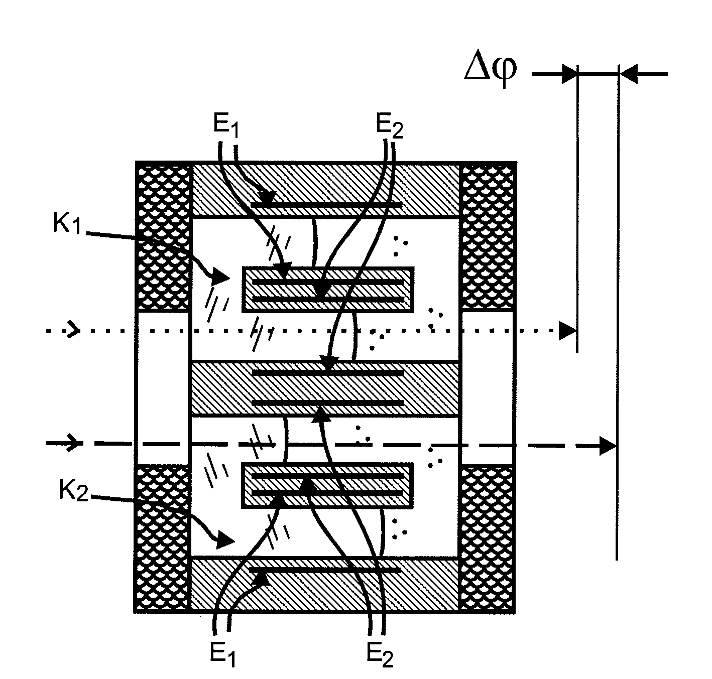
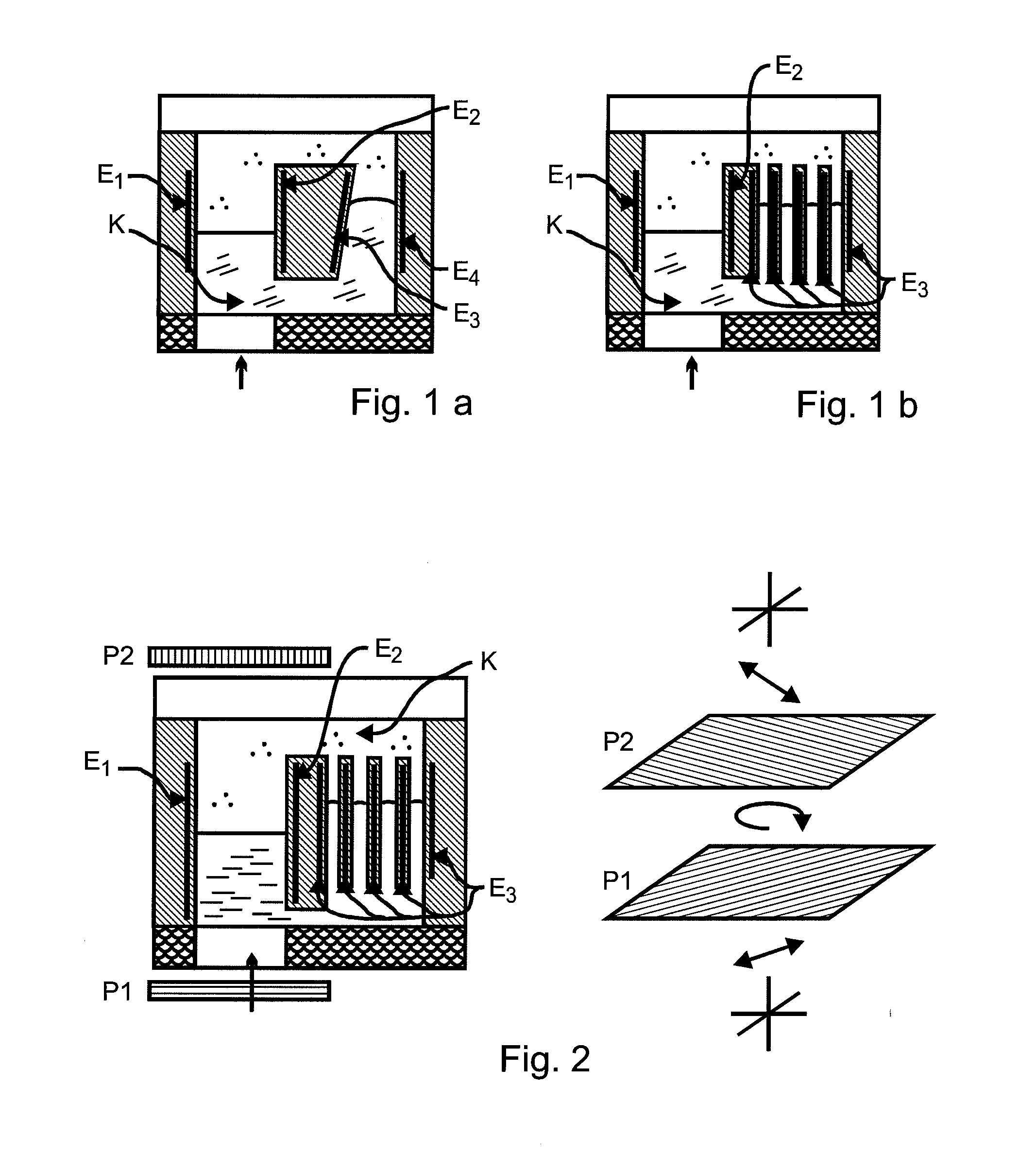
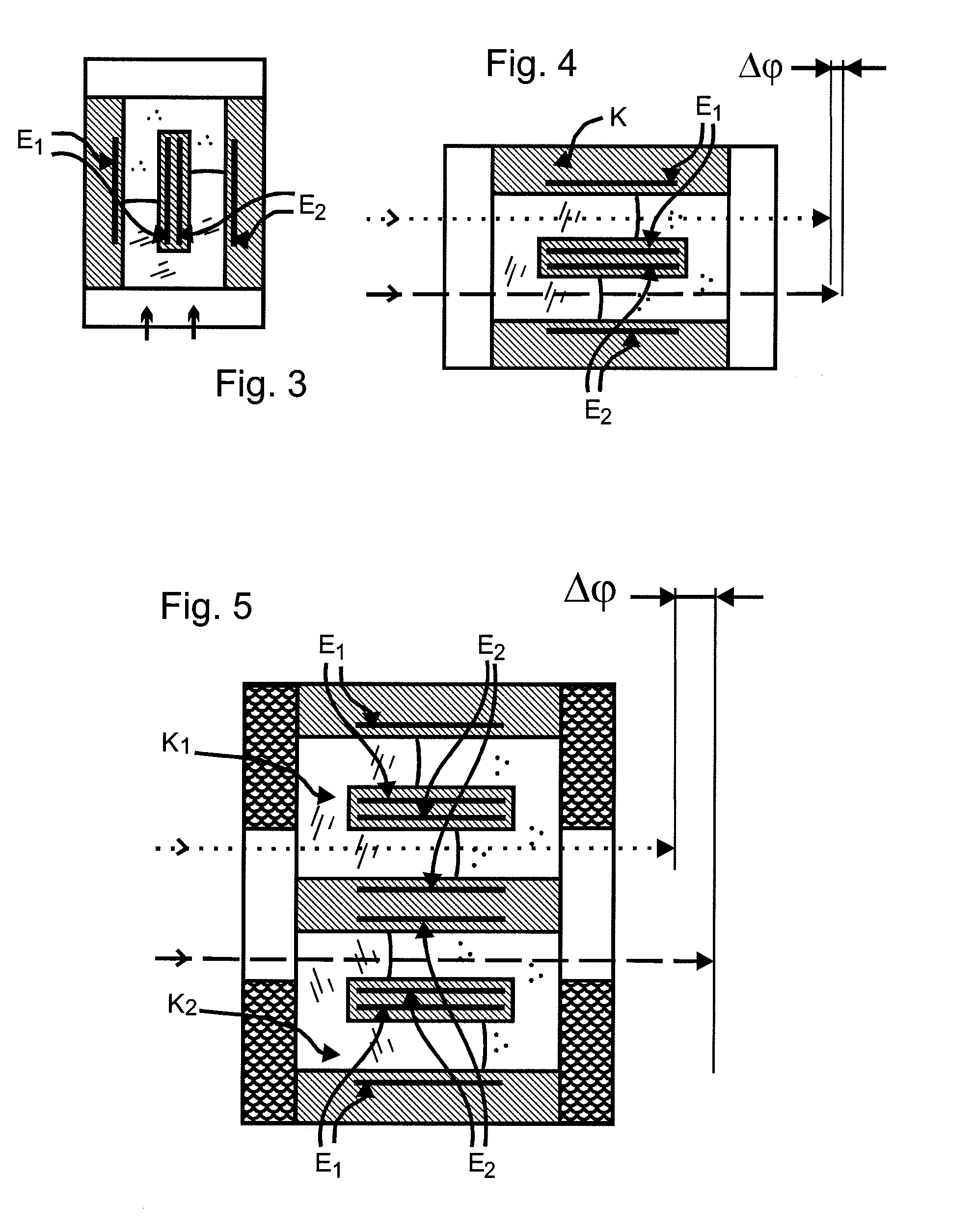
[0062]With the exception of FIG. 6, all Figures show front views of the EW cells in a simplified, schematic manner, but with all details which are essential for the comprehension of the invention. A multitude of these EW cells are arranged in a matrix so to form an array for light modulation. Further essential components of the device according to this invention are pairs of electrodes which are activated by control means. Additional components may be necessary depending on the kind of modulation.

[0063]Each EW cell comprises a chamber with internal and external electrodes, where the internal electrodes are preferably of a transparent nature. At least two immiscible fluids which differ in their refractive index are separated by an interface. A fluid can be a liquid, a gel or a gaseous medium. One fluid of two adjacent fluids is always electrically conductive and can thus be controlled by electrodes. Seen in the direction of light propagation, the first fluid is here the conductive fl...


PUM


Abstract

A modulation device based on electrowetting cells (EW cells), phase or amplitude or both simultaneously as a complex value of incident light is modulated in each EW cell. An EW cell includes at least one chamber with at least two fluids which are separated by an interface, external and internal electrodes which form electrode pairs activatable by control means, where at least one electrode pair controls the level of the interfaces in the chamber. The internal, mutually functionally independent electrodes inside the chamber are disposed parallel to each other such that the chamber is divided into two communicating sections with two controllable interfaces, where at least one section is transparent and forms the optical path. When at least one electrode pair is activated, the interfaces are mutually displaced such that the path length of the pencils of rays is changed compared with an initial value.

Description

CROSS-REFERENCE TO RELATED APPLICATIONS[0001]This application is based on and claims priority to German Application No. DE 10 2008 041 913.3, filed on Sep. 9, 2008, the contents of which are fully incorporated herein by reference.BACKGROUND OF THE INVENTION[0002]1. Field of the Invention[0003]The field of application of the present invention includes e.g. holographic display devices, such as holographic displays which can be used to reconstruct a three-dimensional object (3D object) which consists of multiple object points. Such a holographic display is designed such that either multiple observers are simultaneously displayed the same 3D object, or that the observers can simultaneously watch different, individually selected programmes independently of each other.[0004]2. Description of the Related Art[0005]According to their actual requirement profile, modulator devices comprise a modulator matrix for modulating either the phase or amplitude of almost coherent light in the cells of ...

Claims


Application Information

Patent Timeline
Patent Type & Authority Applications(United States)
IPC IPC(8): G02B26/00
CPCG02B26/004
Inventor FUTTERER, GERALD
Owner SEEREAL TECHNOLOGIES
Why Eureka
Try Eureka