Micro-shutter device and method of manufacturing the same

a micro-shutter and lens technology, applied in the field of micro-shutter devices, can solve the problems of low optical efficiency, 10% of backlight light is effectively transmitted, and it is difficult to block light using only liquid crystals, so as to reduce optical loss and increase optical efficiency

Active Publication Date: 2010-05-13
SAMSUNG ELECTRONICS CO LTD
View PDF8 Cites 50 Cited by
  • Summary
  • Abstract
  • Description
  • Claims
  • Application Information

AI Technical Summary

Benefits of technology

[0010]The following description relates to a micro-shutter device and a method of manufacturing the sam

Problems solved by technology

However, it is impossible to block light using only liquid crystal, and thus polarizing films that transmit only light having a predetermined polarization direction are disposed on front and rear surfaces of the liquid crystal display panel.
While liquid crystal and a polarizing film are used to selectively transmit light in the LCD, the liquid crystal and the polarizing film cause optica

Method used


Image

  • Micro-shutter device and method of manufacturing the same
  • Micro-shutter device and method of manufacturing the same
  • Micro-shutter device and method of manufacturing the same

Examples


Embodiment Construction

[0019]The general inventive concept is described more fully hereinafter with reference to the accompanying drawings, in which exemplary embodiments of the invention are shown. The general inventive concept may, however, be embodied in many different forms and should not be construed as limited to the exemplary embodiments set forth herein. Rather, these exemplary embodiments are provided so that this disclosure is thorough, and will fully convey the scope of the invention to those skilled in the art. In the drawings, the size and relative sizes of layers and regions may be exaggerated for clarity. Like reference numerals in the drawings denote like elements.

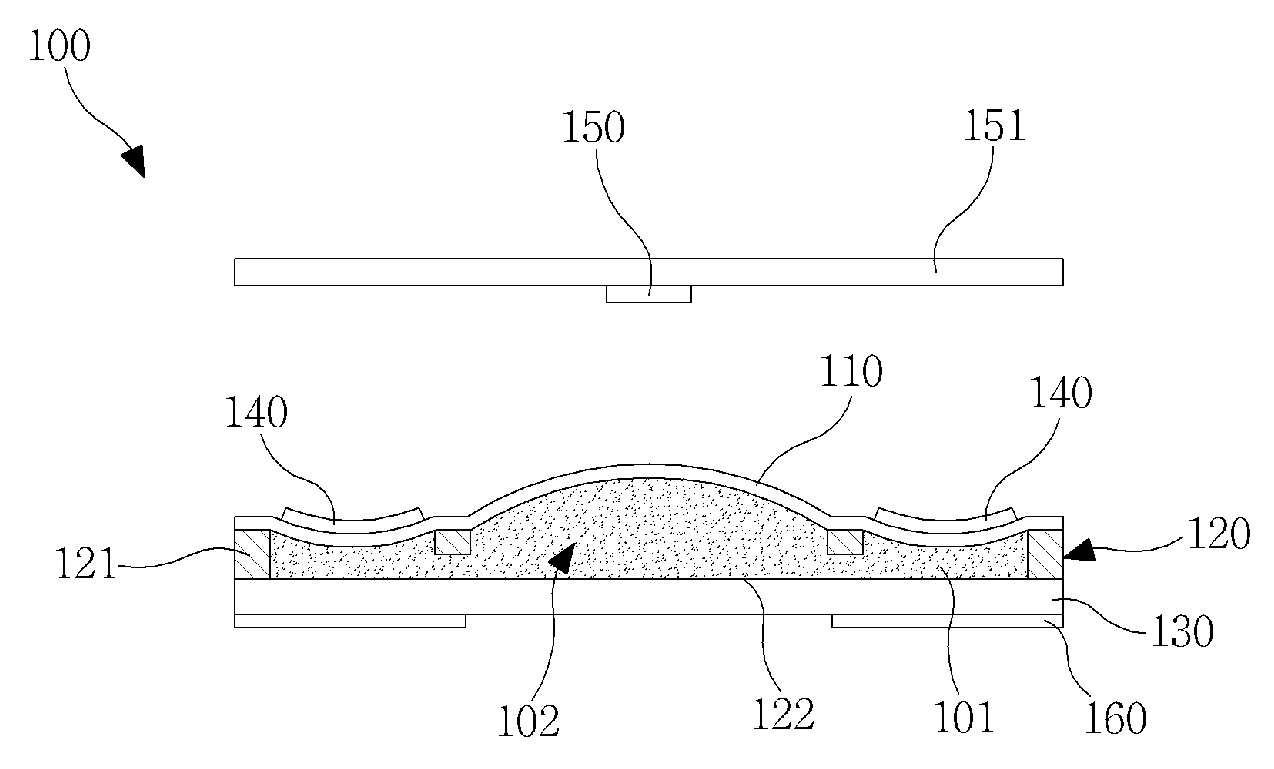
[0020]FIG. 1 is a cross-sectional view of a micro-shutter device according to an exemplary embodiment. Referring to FIG. 1, the micro-shutter device includes a membrane 110, a frame 120, a substrate 130, actuators 140, and a reflector 150.

[0021]The membrane 110 is a flexible thin film, and its shape varies depending on movement o...


PUM

PropertyMeasurementUnit
Poweraaaaaaaaaa
Flexibilityaaaaaaaaaa
Heightaaaaaaaaaa

Abstract

Micro-shutter device applicable to display devices including a flexible display device and method of manufacturing same are provided. Micro-shutter device includes membrane. Frame including receiving hole in its center portion is bonded to membrane. Transparent substrate is bonded to frame to encapsulate optical fluid received in receiving hole. Actuator varies refractive power produced by change in curvature of fluid lens formed in the center portion of the receiving hole due to bending of a periphery of the fluid lens. A reflector is disposed to correspond to the fluid lens and be spaced apart from the membrane, such that light intensity transferred to a user is adjusted depending on the refractive power produced by a change in curvature of the fluid lens. Therefore, the device has improved optical efficiency compared to using liquid crystal and a polarizing film, and can have a flexible structure for application to a flexible display device.

Description

CROSS-REFERENCE TO RELATED APPLICATION[0001]This application claims the benefit of Korean Patent Application No. 10-2008-111003, filed on Nov. 10, 2008, at the Korean Intellectual Property Office, the disclosure of which is incorporated herein in its entirety by reference.BACKGROUND[0002]1. Field[0003]The following description relates to a micro-shutter device and a method of manufacturing the same, and more particularly, to a micro-shutter device applicable to various display devices including a flexible display device and a method of manufacturing the same.[0004]2. Description of the Related Art[0005]Liquid Crystal Displays (LCDs) have better visibility than cathode ray tube (CRT) displays, and are superior to CRT displays of the same display size in terms of average power consumption and heating value. Therefore, LCDs, as well as plasma display panels (PDPs) and field emission displays (FEDs), have attracted considerable attention as next-generation display devices for cellular p...

Claims


Application Information

Patent Timeline
IPC IPC(8): G02B3/14B29D11/00
CPCB29D11/0074G02B26/004G02B5/005G02B3/14
Inventor KIM, WOON-BAEJUNG, KYU-DONGLEE, SEUNG-WAN
Owner SAMSUNG ELECTRONICS CO LTD
Why Eureka
Try Eureka