Container for Electric Energy Storage Device, and Battery and Electric Double Layer Capacitor Using the Same

a technology of electric energy storage and storage containers, which is applied in the direction of cell components, cell casings/cabinets/drawers, cell components, etc., can solve the problems of low manufacturing efficiency, limited cost reduction, and high manufacturing cost, and achieves excellent manufacturing efficiency, high performance, and easy surface mounting

Inactive Publication Date: 2010-05-13
KYOCERA CORP
View PDF14 Cites 36 Cited by
  • Summary
  • Abstract
  • Description
  • Claims
  • Application Information

AI Technical Summary

Benefits of technology

[0010]Accordingly, the invention has been achieved in view of the foregoing problems and its object is to provide a container for electric energy storage device excellent in the manufacturing efficiency and easy for surface mounting to an external electric circuit board, as well as a battery and electric double layer capacitor at high performance using the same.

Problems solved by technology

However, in the battery or the electric double layer capacitor using the container for electric energy storage device shown in FIG. 8, a conductor layer has to be disposed being passed through the ceramic substrate 11 for connecting the first metallized layer 12a with the first electrode C. By such a complicate structure, it involves a problem of requiring a number of steps for manufacturing the ceramic substrate 11 and low manufacturing efficiency.
Further, it also involves a problem that a manufacturing cost is high, and decrease in the cost is limited as well.
Further, the solid electrolyte battery using the container for electric energy storage device shown in FIG. 9 involves a problem that it cannot be surface mounted as it is to an external electric circuit board since charge and discharge are conducted at the bottom plate 22 and the lid member 23 bonded to the lower surface and the upper surface of the ceramic frame 21.
As described above, it involves a problem that the surface mounting to the external electric circuit board is complicated and the operation efficiency of surface mounting is extremely low.

Method used


Image

  • Container for Electric Energy Storage Device, and Battery and Electric Double Layer Capacitor Using the Same
  • Container for Electric Energy Storage Device, and Battery and Electric Double Layer Capacitor Using the Same
  • Container for Electric Energy Storage Device, and Battery and Electric Double Layer Capacitor Using the Same

Examples


Embodiment Construction

[0056]Now referring to the drawings, preferred embodiments of the invention are described below.

[0057]A container for electric energy storage device, as well as a battery or an electric double layer capacitor using the same according to the invention are to be described specifically.

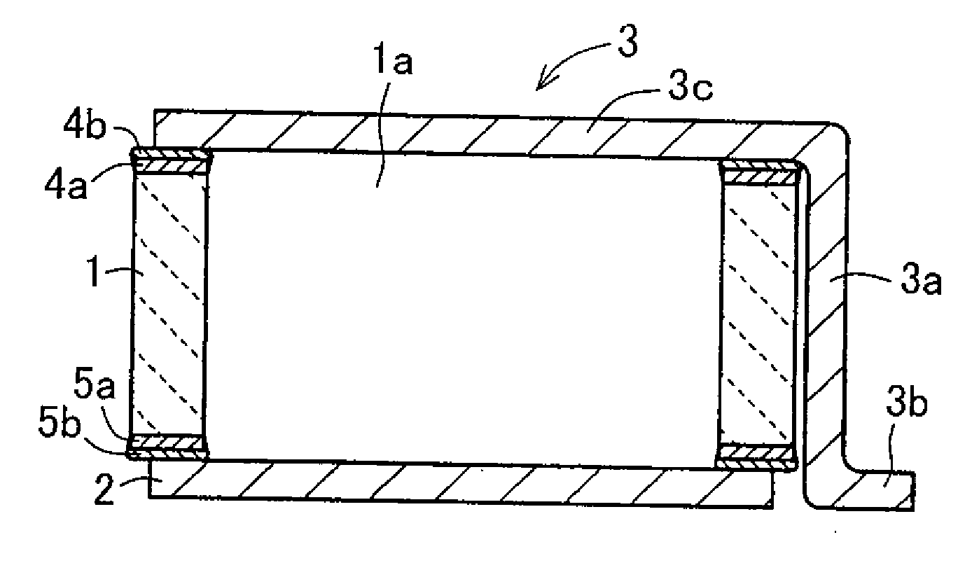
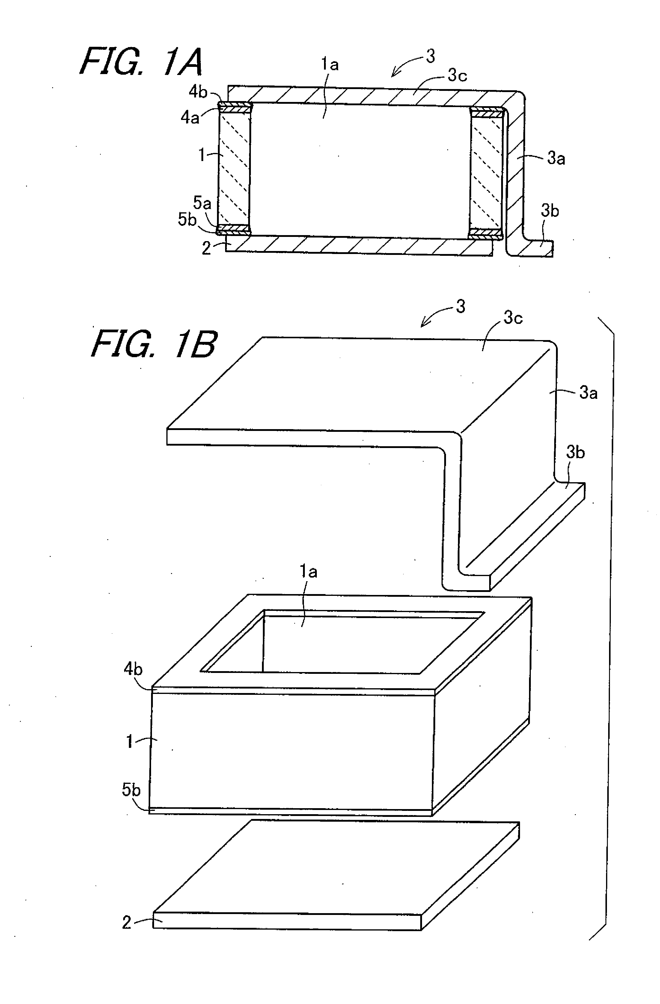
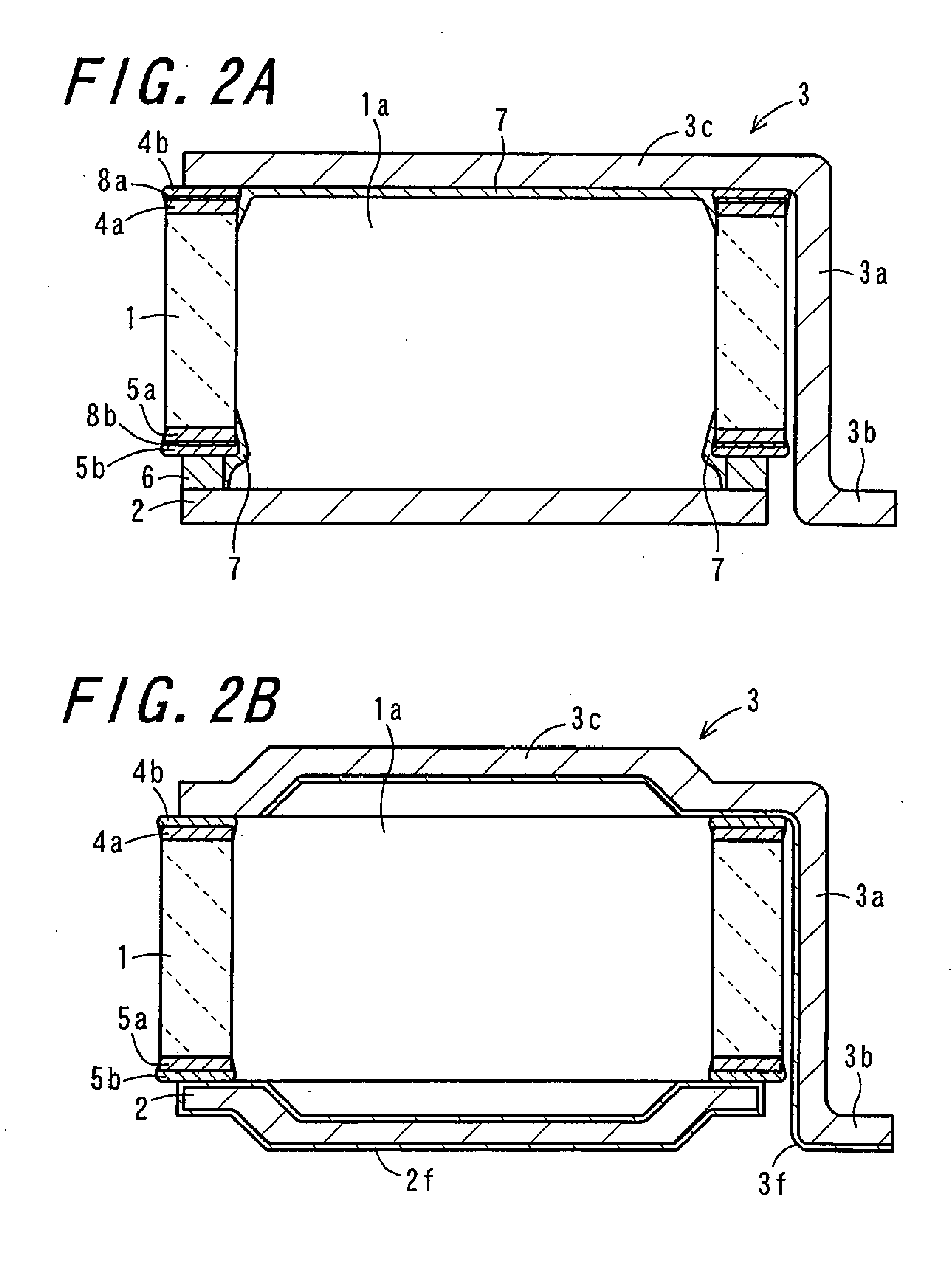
[0058]In FIG. 1A and FIG. 1B, FIG. 1A is a cross sectional view showing a container for electric energy storage device according to a first embodiment of the invention and FIG. 1B is an assembling perspective view of a container for electric energy storage device in FIG. 1A. Further, FIG. 2A is a cross sectional view showing a container for electric energy storage device according to a second embodiment of the invention. FIG. 2B is a cross sectional view showing a container for electric energy storage device according to a third embodiment of the invention. FIG. 3 is a perspective assembling view showing a container for electric energy storage device according to a fourth embodiment of the invention. FIG...


PUM

PropertyMeasurementUnit
thicknessaaaaaaaaaa
heightaaaaaaaaaa
heightaaaaaaaaaa

Abstract

The invention relates to a container for electric energy storage device excellent in the manufacturing efficiency and easy for surface mounting to an external electric circuit board, and a battery and electric double layer capacitor at high performance using the same. A container for electric energy storage device includes a frame (1), a first sealing member (2) bonded to the frame (1) so as to close a first opening of the frame (1), and a second sealing member bonded to the frame (1) so as to close a second opening of the frame (1) and having a connection end portion disposed side by side with the first sealing member (2). The container for electric energy storage device can be manufactured through a simple manufacturing process and can be surface-mounted easily.

Description

TECHNICAL FIELD[0001]The present invention relates to a container for electric energy storage device for use in a chargeable battery or electric double layer capacitor, and a battery or electric double layer capacitor using the same. More specifically, the present invention relates to a thin battery used for small-sized electronic equipment such as cellular phones, a battery for an electric double layer capacitor for use in a backup power source of semiconductor memories, and stand-by power sources for electronic equipments, or an electric double layer capacitor and a container for electric energy storage device.BACKGROUND ART[0002]In recent years, along with remarkable development of portable equipment typically represented by cellular phones, portable computers, and camera-integrated video tape recorders, further decrease in the size and weight have been demanded. Then, also for the battery as the power source for such portable equipments, it has been demanded to increase the ener...

Claims


Application Information

Patent Timeline
Patent Type & Authority Applications(United States)
IPC IPC(8): H01M2/00H01G9/10H05K5/06H01G11/74H01G11/78H01G11/80H01M50/553
CPCH01G9/016H01G9/08H01G9/155H01G11/74H01G11/78Y02E60/13H01M2/0217H01M2/0225H01M2/1022H01M2/30H01G11/80Y02E60/10H01M50/56H01M50/103H01M50/553
Inventor USHIO, YOSHIHIROMIYAISHI, MANABUYOKOI, KIYOTAKATANAKA, NOBUYUKI
Owner KYOCERA CORP
Why Eureka
Try Eureka