Partial or complete prosthetic replacement arthroplasty of the distal radioulnar joint
a technology prosthetic replacement, which is applied in the field of distal radioulnar joint, can solve the problems of subluxation (partial dislocation) or dislocation, acute pain, and damage to the druj, and achieve the effect of ensuring the durability of the join
- Summary
- Abstract
- Description
- Claims
- Application Information
AI Technical Summary
Benefits of technology
Problems solved by technology
Method used
Image
Examples
example 1
Ulnar Prostheses with an Integral Plate
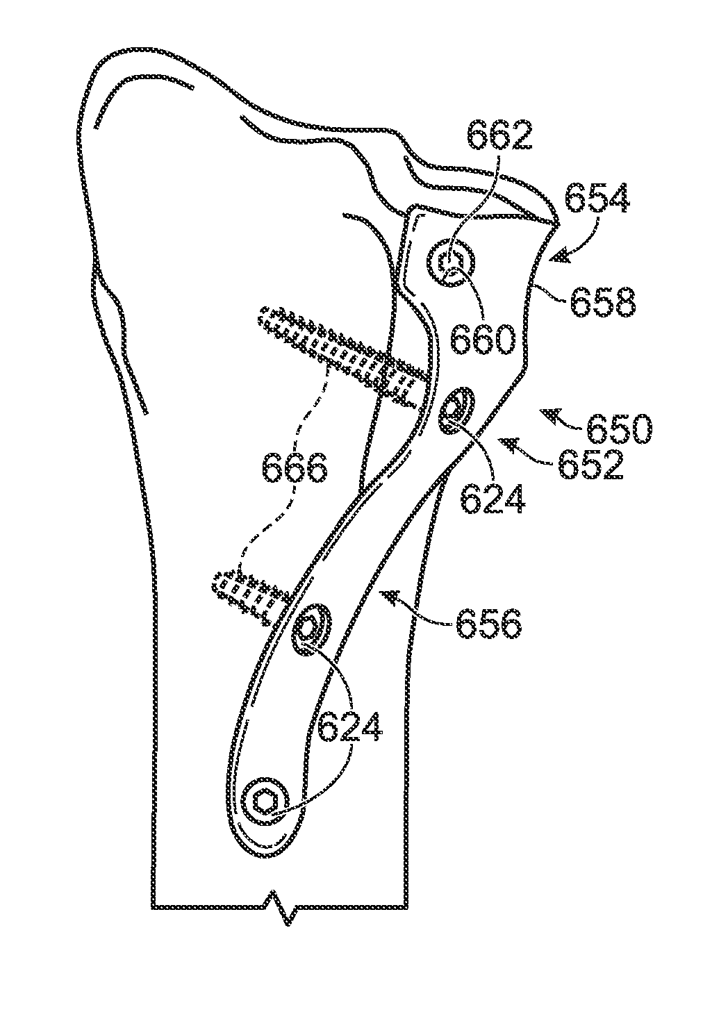
[0104]This example describes exemplary ulnar prostheses equipped with a plate portion extending from a prosthetic head portion; see FIGS. 30 and 31.
[0105]FIG. 30 shows a dorsal view of distal ulna 58 with the seat and pole of the distal ulnar head resected and replaced by another exemplary ulnar prosthesis 450. The ulnar prosthesis may include a head portion 452 connected to a plate portion 454.
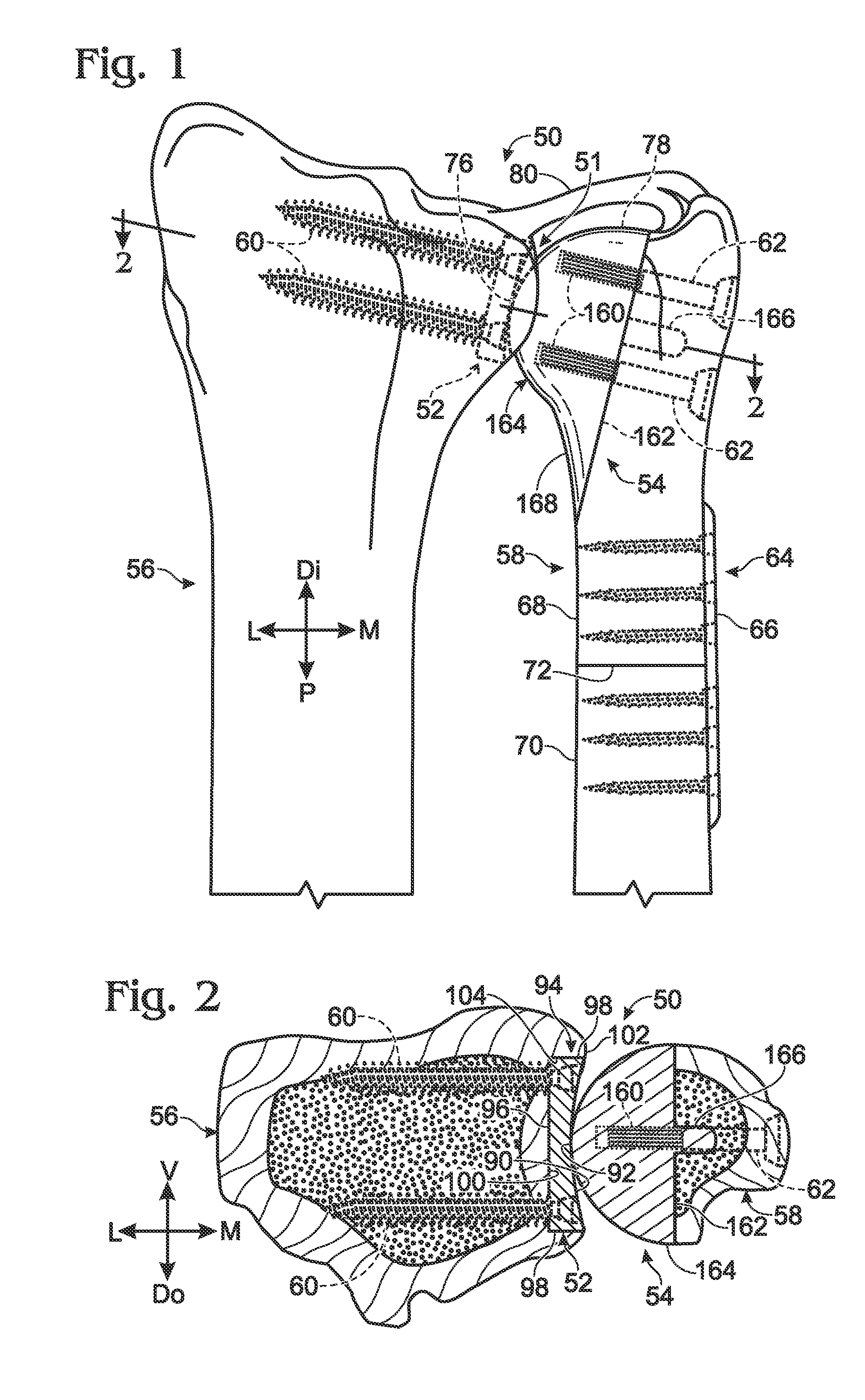
[0106]Head portion 452 may have any suitable features. The head portion may be shaped in at least general correspondence with, and may include a convex replacement surface 456 for, the resected region of the distal ulnar head. Replacement surface 456 may be at least generally spherical or cylindrical, among others. The head portion may be attached to bone using a stem, fasteners, or the like (e.g., see ulnar prosthesis 54 of FIG. 1). The head portion also may be designed to provide soft tissue fixation. In particular, the head portion may define at least...
example 2
Arthroplasty of the Distal Radioulnar Joint with Reverse Prostheses
[0109]This example describes replacement of radial and ulnar surfaces of the distal radioulnar joint with a “reverse” radial prosthesis 500 and a “reverse” ulnar prosthesis 502 that supply respective convex and concave articulation surfaces 504, 506, the reverse of the joint anatomy; see FIG. 32.
[0110]Radial prosthesis 500 may have a generally spherical body 508 and a stem 510 projecting from an inner surface 512 of body 508. Body 508 may define apertures that receive fasteners 514 in a “forward” (medial to lateral) direction or a “retrograde” (lateral to medial) direction. In exemplary embodiments, inner surface 512 may be flat and body 508 may be a frustospherical.
[0111]Ulnar prosthesis 502 may be secured on a cut surface of ulna 58 using fasteners 516. For example, the prosthesis may have a flat inner surface 518 that abuts a cut face 520 of ulna 58 formed by partial resection of the lateral aspect of the distal u...
example 3
Replacement of the Ulnar Seat and Pole with an Ulnar Cap
[0113]This example describes installation and use of an exemplary ulnar prosthesis 540 structured as an ulnar cap; see FIGS. 33 and 34.
[0114]FIG. 33 shows a dorsal view of distal ulnar fragment 68 disposed in a reflected configuration after osteotomy, which exposes an ulnar portion 542 of the distal radioulnar joint to permit resurfacing thereof. A resurfacing bit 544 with a concave reshaping region 546 may be advanced against the lateral aspect of distal ulnar head 216 to modify ulnar portion 542. Rotary action of bit 544 may remove cartilage and / or subchondral bone, to prepare head 216 for receiving ulnar prosthesis 540 (see FIG. 34).
[0115]FIG. 34 shows distal ulnar fragment 68 after reshaping head 216 with bit 544 (FIG. 33) to form a lateral knob 548. One or more bores 550 also may be formed in the knob. Ulnar prosthesis 540 then may be installed on knob 548. Prosthesis 540 may have a concave inner surface 552 that is comple...
PUM
 Abstract
Description
Claims
Application Information
 - R&D
- Intellectual Property
- Life Sciences
- Materials
- Tech Scout
- Unparalleled Data Quality
- Higher Quality Content
- 60% Fewer Hallucinations
Browse by: Latest US Patents, China's latest patents, Technical Efficacy Thesaurus, Application Domain, Technology Topic, Popular Technical Reports.
© 2025 PatSnap. All rights reserved.Legal|Privacy policy|Modern Slavery Act Transparency Statement|Sitemap|About US| Contact US: help@patsnap.com


