Vehicle and traffic system

a technology of traffic system and vehicle, applied in the field of vehicles and traffic systems, to achieve the effect of no generation, excellent environmental effects and performances, and high degree of operation freedom of vehicles

Inactive Publication Date: 2010-05-13
TAKESHIMA NAGAE +1
View PDF8 Cites 38 Cited by
  • Summary
  • Abstract
  • Description
  • Claims
  • Application Information

AI Technical Summary

Benefits of technology

[0014]In accordance with the present invention, the overhead line(s) is / are utilized, which allows supply of electric power therefrom to vehicle(s) being in the state of traveling on road(s), and also the battery in the vehicle(s) may be charged from the overhead line(s) so that the vehicle will continue to run on ordinary roads having no such overhead line(s), hence providing a high degree of operation freedom of the vehicles. In addition, the vehicle uses electricity as its energy and therefore provides excellent eco-friendly effects and performances, such as no emission of exhaust and no generation of undesired noise.

Problems solved by technology

However, the aforementioned prior arts are all designed for use with public transportation facilities, such as electric tramway and trolley bus, and not intended for any private transportation means, such as a private automobile, which has a high degree of freedom for its operation and travel in comparison with the public transportation facilities.

Method used


Image

  • Vehicle and traffic system
  • Vehicle and traffic system
  • Vehicle and traffic system

Examples


embodiment 1

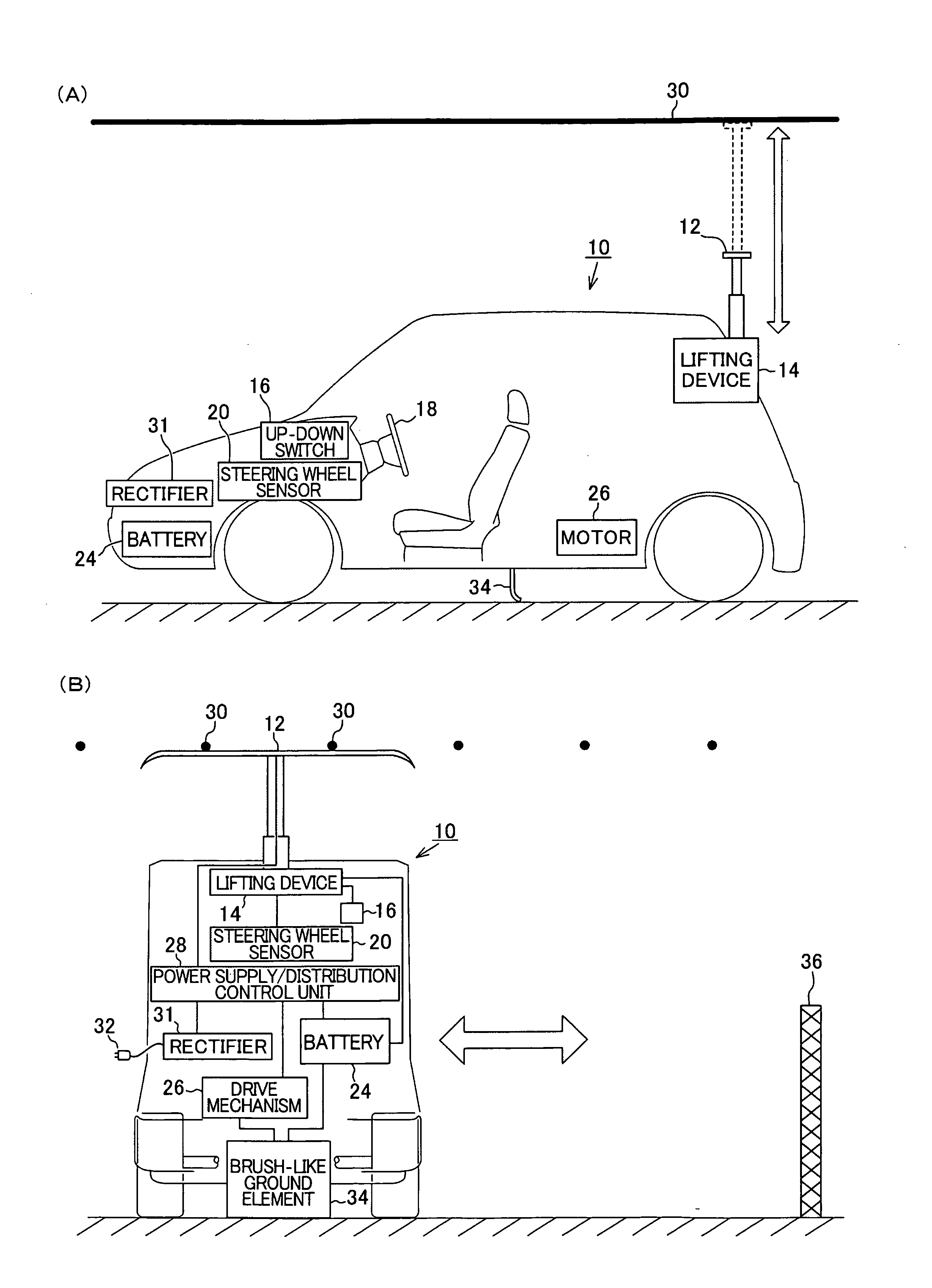
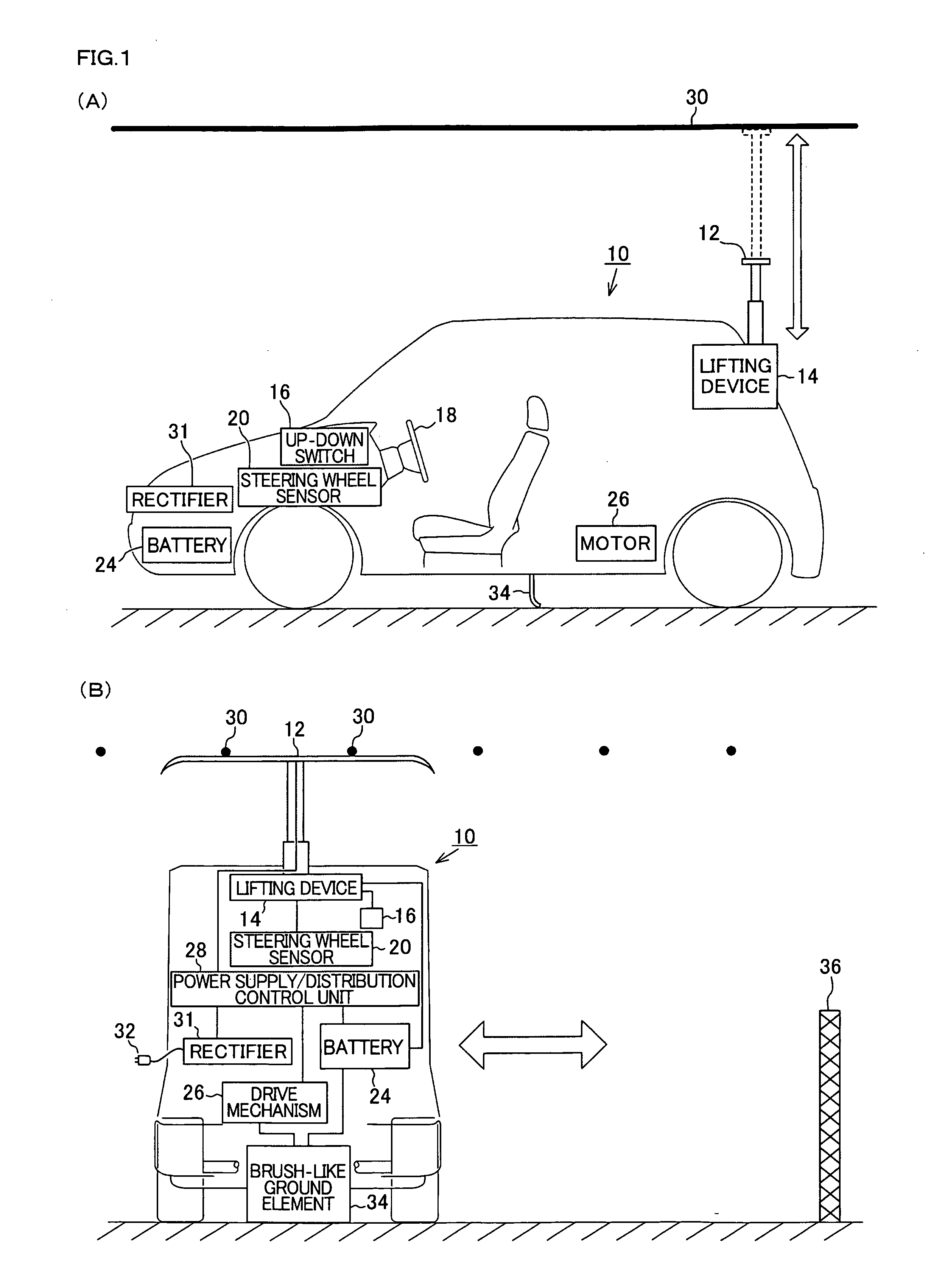
[0061]First of all, referring to FIGS. 1 to 3, a description will be made of a 1st embodiment of the present invention. FIG. 1(A) is a diagram illustrative of principal constituent parts arranged in a vehicle 10 as applied to the present embodiment. FIG. 1(B) schematically shows how the vehicle is to be controlled and driven on the road. In those two Figures, it is to be understood that, as similar to ordinary electric vehicle driven by electric motor, the vehicle 10 of the present embodiment is provided with steering wheel, seats, front and rear wheels, a speedometer, an accelerator pedal, a brake pedal, and so forth.

[0062]In the illustrative embodiment, an electric power collector 12 is disposed at a point rearwardly and upwardly of the vehicle 10. And also, arranged above the road are a plurality of overhead lines 30 adapted for feeding electric power to vehicles, such that, for example, the overhead lines extend abreast along the road in a 10-cm spaced-apart relation with one an...

embodiment 2

[0078]With reference to the illustrations shown in FIG. 4, the 2nd embodiment of the present invention will now be described, hereinafter. FIG. 4(A) shows one variant of the present embodiment wherein a plurality of overhead lines 400 are shown and transversal lines 402 are electrically connected with those overhead lines 400, whereby all the overhead lines 400 are in an electrically connected relation with one another. Namely, each of the transversal lines 402 extends transversely of all the overhead lines 400 and has an electrical connection with each of the all overhead lines 400 and, with that arrangement, even if many vehicles running on the road happen to intensively cause their all electric power collectors to contact one overhead line 400 or one particular pair of the overhead lines 400, an electric power is then supplied from other remaining overhead lines 400, via the transversal lines 402, to the overhead line(s) 400 in question with which many vehicles are now connecting...

embodiment 3

[0079]Referring to FIG. 5, a 3rd embodiment of the present invention will be described, hereinafter. In the FIG. 5, there is illustrated a vehicle 500 basically similar in structure to the vehicle described previously, except that it has an electric power collector 502 which comprises a ringed contact element 502A and a generally T-shaped support rod 502B, such that the ringed contact element 502A is supportively connected with the lifting device 506 by that support rod 502B. The ringed formation of contact element 502A has the advantage that, irrespective of any direction in which the vehicle 500 may move towards the overhead lines, the ringed contact element 502A is positively brought in a sufficient contact with the overhead lines. Further, according to the present embodiment, an overhead line detection sensor 504 is shown as being electrically connected with the lifting device 506. The overhead line detection sensor 504 is adapted for detecting the presence and absence of overhe...


PUM


Abstract

Provided are a vehicle having high degree of operation freedom due to electric power being able to be supplied to the vehicle during its travel and due to the vehicle being able to drive on normal roads, and a traffic system. A large number of overhead lines are arranged over a road. An extendable electric power collector is provided at the rear of the vehicle, and a battery and a drive mechanism are mounted on the vehicle. When the power collector is in contact with an overhead line, electric power supplied from the overhead line is supplied to the battery to charge it and electric power is supplied also to the drive mechanism. When the vehicle travel on a normal road having no such overhead lines, electric power is supplied from the battery to the drive mechanism.

Description

TECHNICAL FIELD[0001]The present invention relates to a traffic system which utilizes electricity as a power for transportation purpose. More particularly, the invention is directed to an improvement of the traffic system of this kind intended for a vehicle(s) having buttery provided therein, which is designed to allow the vehicle to be electrically propelled for travel on roads through electric power stored in the buttery.BACKGROUND ART[0002]There has been known a traffic system that allows vehicle to be electrically propelled for travel on roads through electric power stored in a buttery provided in the vehicle and also allows for supply of electric power form overhead lines to the vehicle. Examples of such vehicle and traffic system include the under-listed patent prior-art materials, namely, the patent literature Nos. 1 to 4. All those prior arts commonly disclose a traffic system wherein overhead lines are arranged in a particular zone, such that electric power may be supplied ...

Claims


Application Information

Patent Timeline
Patent Type & Authority Applications(United States)
IPC IPC(8): G06F7/00E01C1/00
CPCB60K1/00B60K1/04B60L5/28B60L5/36B60L9/00B60L2200/26B60L11/1809B60M7/006Y02T10/7005Y02T90/14B60L11/1801Y02T10/7072B60L50/53B60L53/00Y02T10/70
Inventor TAKESHIMA, NAGAETAKESHIMA, YOSHIHITO
Owner TAKESHIMA NAGAE
Why Eureka
Try Eureka