Method of estimating physical parameters of a geological formation

a geological formation and physical parameter technology, applied in the field of methods of estimating physical parameters of geological formations, can solve the problems of not making it possible to estimate the position of leakage, not making it possible to obtain physical parameters of several layers of materials,

Active Publication Date: 2010-05-13
TOTAL PUTEAUX FR
View PDF12 Cites 4 Cited by
  • Summary
  • Abstract
  • Description
  • Claims
  • Application Information

AI Technical Summary

Benefits of technology

[0005]The present invention aims to measure physical parameters of the subsoil by being less subject to such limitations.

Problems solved by technology

This method does not make it possible to estimate the position of the leak, or estimate physical parameters of the materials surrounding the well at a given depth.
Furthermore, this method does not make it possible to obtain physical parameters of several layers of materials in the well.

Method used


Image

  • Method of estimating physical parameters of a geological formation
  • Method of estimating physical parameters of a geological formation
  • Method of estimating physical parameters of a geological formation

Examples


second embodiment

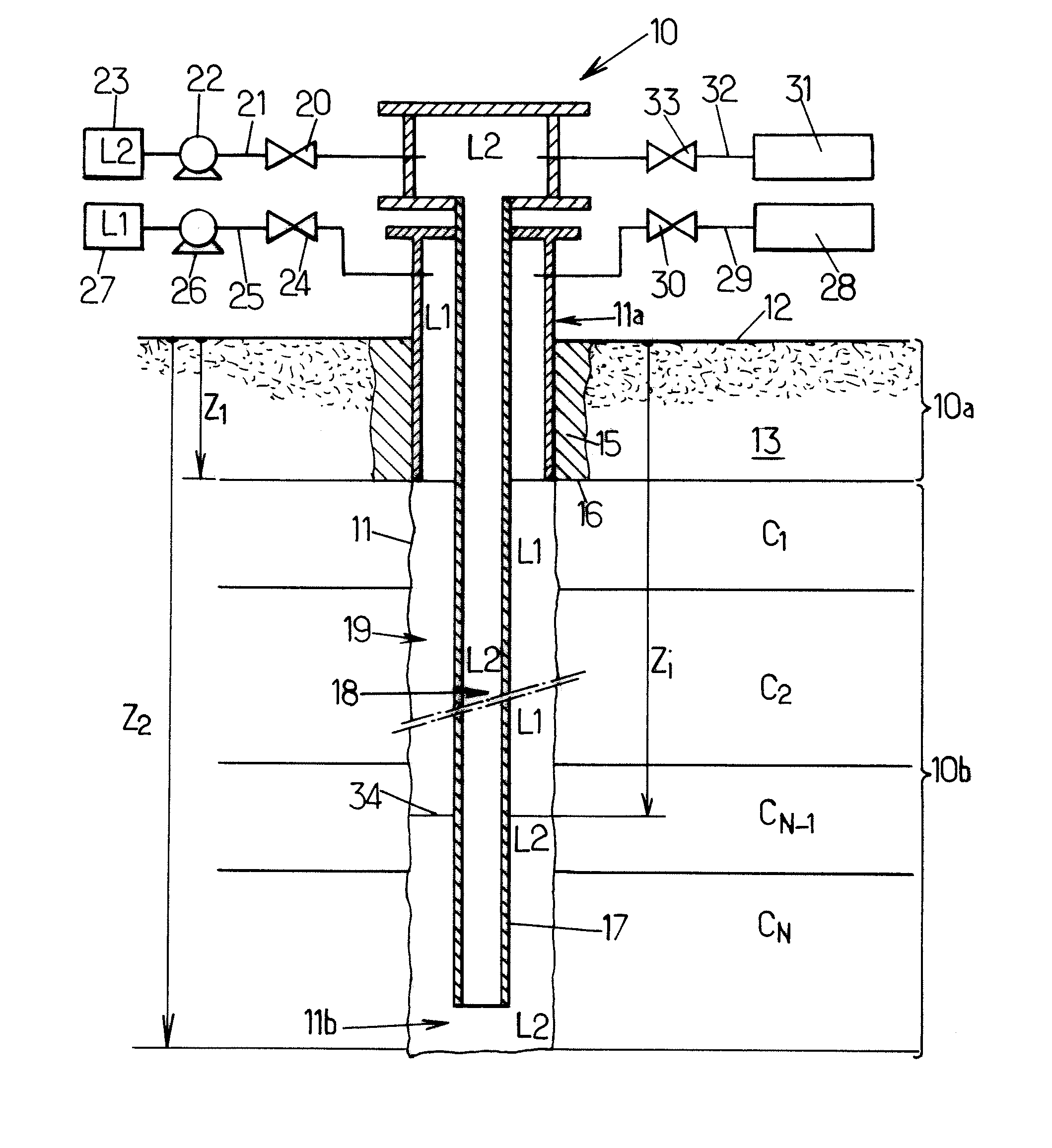
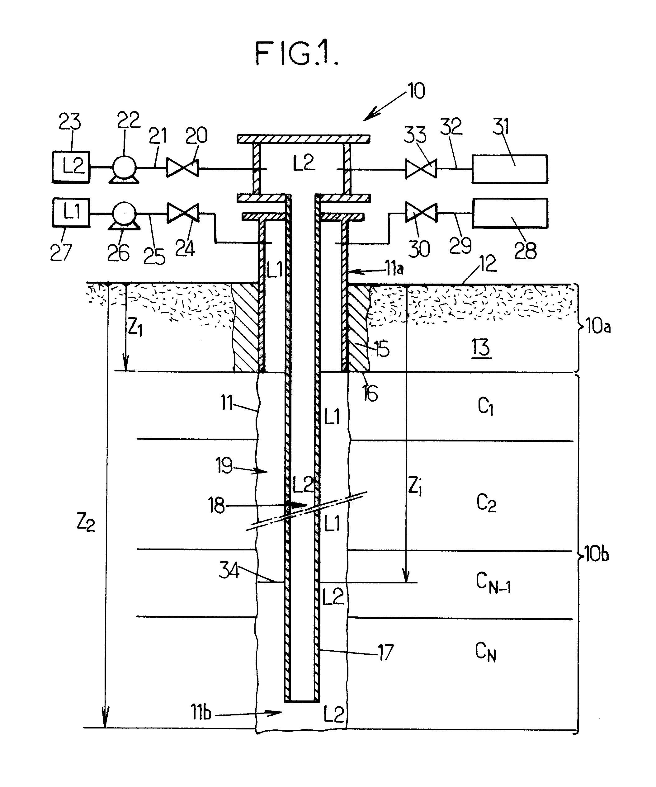
[0149]FIGS. 5a to 5c present the method, in which the well is equipped with a system of servo-controlling a reference pressure Pref, so that said reference pressure is held substantially constant at a value Pc as represented in FIG. 5a.

[0150]The lines 21, 25 are then, for example, each equipped with a flow rate measuring device to measure at each instant the flow rates and / or volumes of the fluids injected and removed at the well head.

[0151]The servo-control or closed-loop control system then controls the pumps 22, 26 to automatically inject or remove a certain quantity of fluid to keep said reference pressure Pref constant.

first embodiment

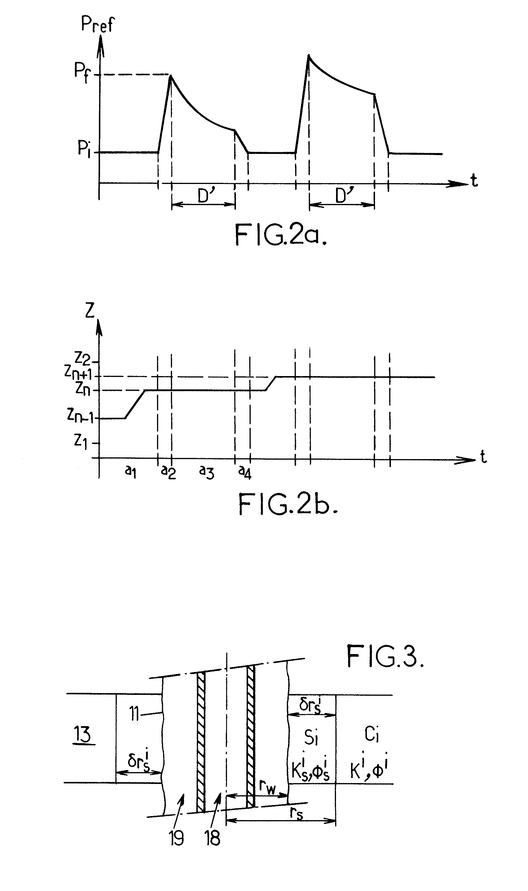
[0152]Well head flow rates Qannwh and Qtubwh are measured during the tests, FIG. 5b showing an example of the trend of a reference flow rate Qref during a test sequence similar to that of the method represented by FIGS. 2a and 2b. These flow rates can be used to estimate the permeation flow rates Q1 and Q2 of the liquid L1 and L2, respectively, in a manner similar to the calculations presented previously for the well head pressures.

[0153]FIG. 5c then represents in this embodiment the trends of the depth zi of the interface 34 during said test sequence.

[0154]The calculated variations of pressures and / or flow rates at the well head can then also be calculated.

[0155]The comparison of the trends of the measured and simulated quantities can therefore be performed equally on pressures or flow rates, to identify an optimum set of values for the physical parameters of the geological formation 13.

[0156]Also, the methods described implement disturbance sequences of the hydraulic balance of th...


PUM


Abstract

A well passing through a geological formation is fitted with a tube, open at its bottom end, that is filled with a fluid. Another fluid is in the annular space between the tube and the wall of the well, the two fluids exhibiting an interface situated in the annular space. A hydraulic balance of the fluids of the well is disturbed and the trend of certain quantities is measured. These measurements are moreover simulated by computer by using different sets of values for the physical parameters, and efforts are made to estimate the geological formation. A comparison of the measurements with the simulation results makes it possible to identify an optimum set of values for the parameters.

Description

FIELD OF THE INVENTION[0001]The present invention relates to the determination of physical parameters of layers of materials in the subsoil.BACKGROUND OF THE INVENTION[0002]The object of the method is to find properties such as the permeability, the porosity or the natural pressure, of the layers of materials in the subsoil. The knowledge of such properties is notably useful if exploitation of the subsoil is envisaged, for example to extract hydrocarbons therefrom.[0003]Document FR-A-2 747 470 describes a method of testing seal-tightness of a subterranean fluid storage cavity. According to this method, the cavity and a well that gives access to it from the surface are filled with two non-miscible fluids, the interface between the two fluids being positioned at a desired depth. To simulate a leak at this depth, predetermined quantities of one of the two fluids are injected or subtracted. The pressures at the well head are measured, together with the position of the interface before a...

Claims


Application Information

Patent Timeline
Patent Type & Authority Applications(United States)
IPC IPC(8): G06F19/00G06G7/48
CPCG01V9/00E21B49/008
Inventor JACQUES, ANTOINEBOUTAUD DE LA COMBE, JEAN-LUCBEREST, PIERREBROUARD, BENOIT
Owner TOTAL PUTEAUX FR
Why Eureka
Try Eureka