

Light-Emitting Element, Light-Emitting Device, Electronic Device, and Lighting Device
- Summary
- Abstract
- Description
- Claims
- Application Information
AI Technical Summary
Benefits of technology
Problems solved by technology
Method used
Image

Examples
embodiment 1
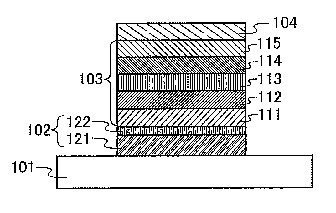
[0067]In this embodiment, one mode of the light-emitting element to which one embodiment of the present invention is applied will be described using FIG. 1.
[0068]A light-emitting element described in this embodiment has a plurality of layers between a pair of electrodes. The plurality of layers are a stack of layers each including a substance with a high carrier-injection property or a substance with a high carrier-transport property such that a light-emitting region is formed in a region away from the electrodes, i.e., such that carriers recombine in an area away from the electrodes.
[0069]In this embodiment, the light-emitting element includes a first electrode 102, a second electrode 104, and an EL layer 103 provided between the first electrode 102 and the second electrode 104. Note that description will be made below in this embodiment on the assumption that the first electrode 102 functions as an anode and the second electrode 104 functions as a cathode. In other words, the desc...
embodiment 2
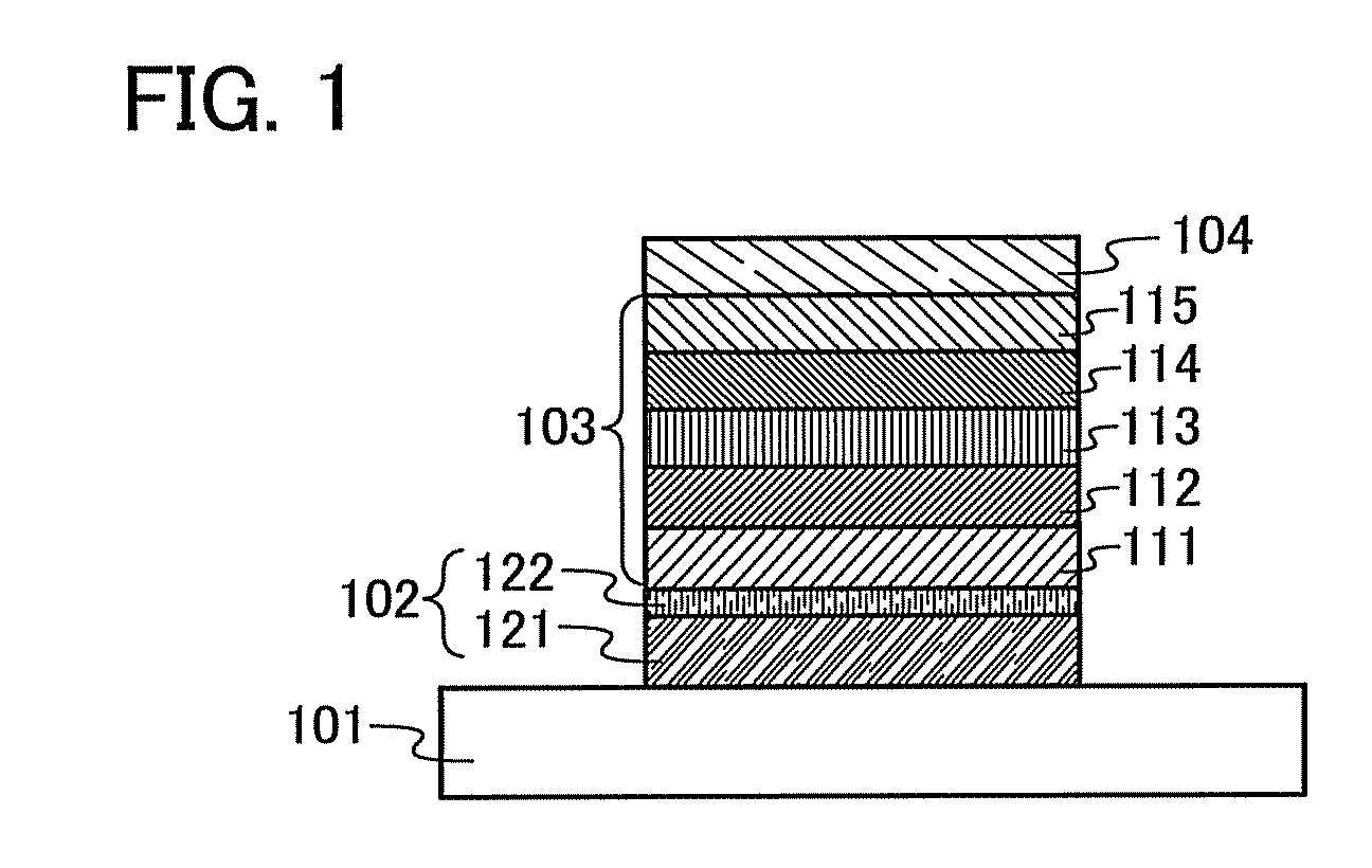
[0116]In this embodiment, description is provided for a mode of a light-emitting element with a structure in which plural light-emitting units of one embodiment of the present invention are stacked (hereinafter referred to as a stacked type light-emitting element) with reference to FIG. 2. This light-emitting element is a stacked type light-emitting element having a plurality of light-emitting units between a first electrode and a second electrode. Each light-emitting unit can have a structure similar to the structure described in Embodiment 1. In other words, the light-emitting element shown in Embodiment 1 is a light-emitting element having one light-emitting unit.
[0117]In FIG. 2, a first light-emitting unit 511 and a second light-emitting unit 512 are stacked between a first electrode 501 and a second electrode 502, and a charge generation layer 513 is provided between the first light-emitting unit 511 and the second light-emitting unit 512. The structures described in Embodiment...
embodiment 3
[0126]In this embodiment, a light-emitting device including a light-emitting element of one embodiment of the present invention is described.
[0127]In this embodiment, a light-emitting device including a light-emitting element described in Embodiments 1 and 2 in a pixel portion will be described with reference to FIGS. 3A and 3B. FIG. 3A is a top view of the light-emitting device, and FIG. 3B is a cross sectional view taken along lines A-A′ and B-B′ of FIG. 3A. This light-emitting device includes a driver circuit portion (source side driver circuit) 601, a pixel portion 602, and a driver circuit portion (gate side driver circuit) 603 which are configured to control the light emission of the light-emitting element. A reference numeral 604 represents a sealing substrate, a reference numeral 605 represents a sealant, and the inside surrounded by the sealant 605 is a space 607.
[0128]A lead wiring 608 is a wiring for transmitting signals that are to be inputted to the source side driver c...
PUM
 Abstract
Description
Claims
Application Information