Localization system and localization method
- Summary
- Abstract
- Description
- Claims
- Application Information
AI Technical Summary
Benefits of technology
Problems solved by technology
Method used
Image

Examples
first embodiment
[0049]First, a configuration of the localization system is described.
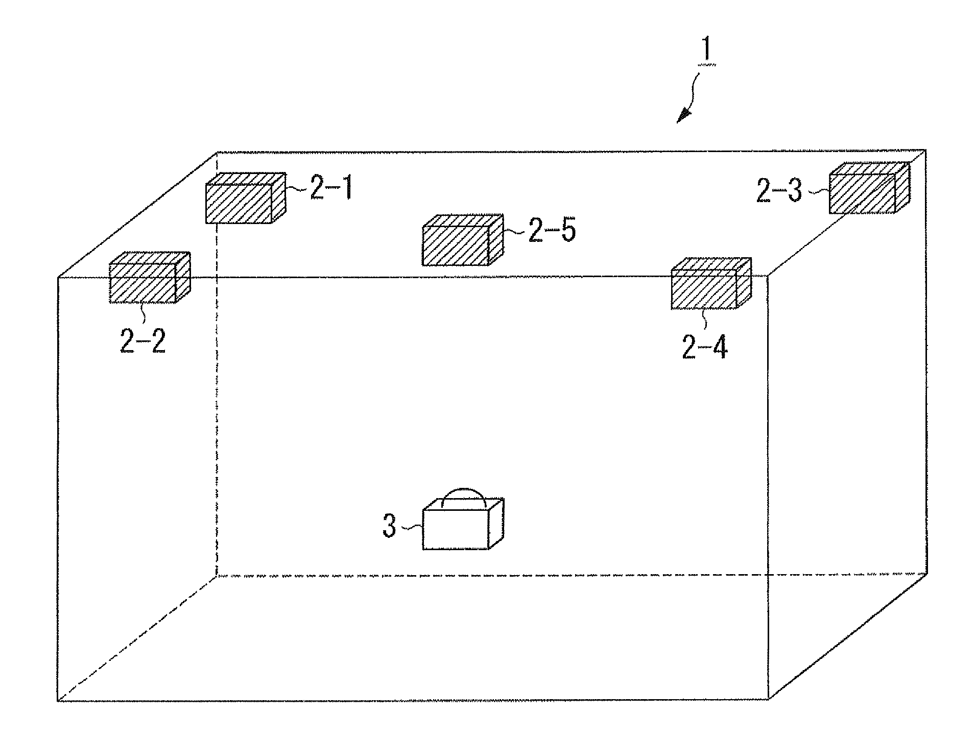
[0050]FIG. 1 is a system configuration diagram representing a system configuration of the position measurement system 1. The position measurement system 1 includes five luminescent devices 2-1 to 2-5 and a position measurement device 3. Hereinafter, features that are in common with the luminescent devices 2-1 to 2-5 will be described by simply referring to “the luminescent device 2.” The luminescent device 2 is fixed on a ceiling of an interior of a room in which the position measurement system 1 is placed. The luminescent device 2 is fixed on the ceiling so that the luminescent side of the luminescent device 2 faces the floor of the room. The position measurement device 3 receives light from a plurality of luminescent devices 2. The position measurement device 3 measures the position of the own device based on the light that was received.
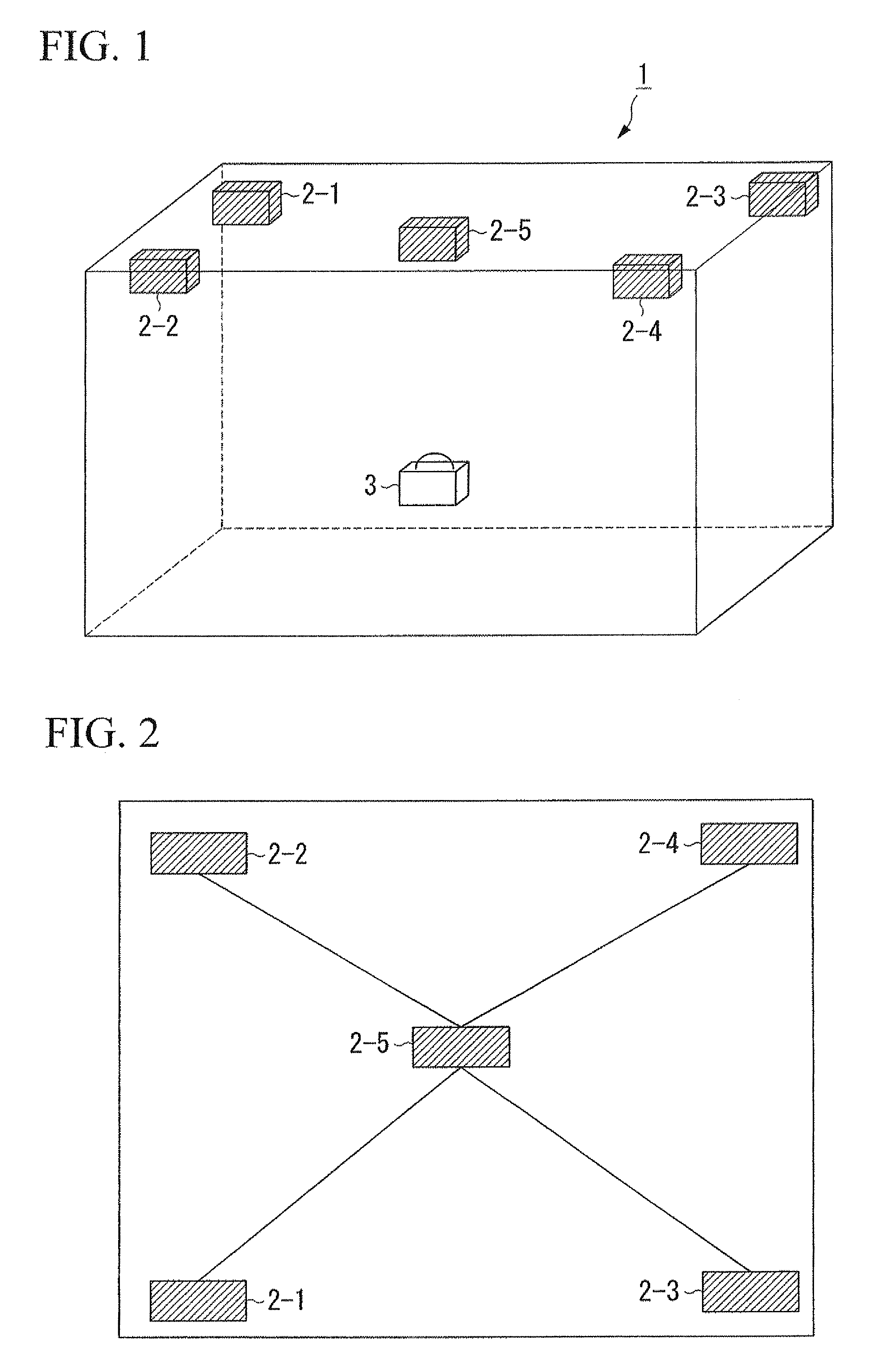
[0051]FIG. 2 is a diagram representing an example of an arrangement of the lu...
second embodiment
[0096]Hereinafter, a second embodiment is described. FIG. 19 is a skeletal block diagram representing the functional configuration of a luminescent device 2b which is a second embodiment of the luminescent device 2 of the position measurement system 1. The functional unit that is the same as that of the luminescent device 2a of the first embodiment is referred to in FIG. 19 using the same reference numeral used in FIG. 3, and will not be described again.
[0097]The luminescent device 2b is different from the luminescent device 2a in that the luminescent device 2b includes a luminescent unit 202b instead of the luminescent unit 202a. Otherwise, the configuration of the luminescent device 2b is the same as that of the luminescent device 2a. The luminescent unit 202b includes a first luminescent unit for measurement 205, a second luminescent unit for measurement 206, a third luminescent unit for measurement 207, and a luminescent unit for identification 204.
[0098]The first luminescent un...
PUM
 Abstract
Description
Claims
Application Information
 - Generate Ideas
- Intellectual Property
- Life Sciences
- Materials
- Tech Scout
- Unparalleled Data Quality
- Higher Quality Content
- 60% Fewer Hallucinations
Browse by: Latest US Patents, China's latest patents, Technical Efficacy Thesaurus, Application Domain, Technology Topic, Popular Technical Reports.
© 2025 PatSnap. All rights reserved.Legal|Privacy policy|Modern Slavery Act Transparency Statement|Sitemap|About US| Contact US: help@patsnap.com