Working electrode, dye-sensitized solar cell having same and method for making same

a solar cell and working electrode technology, applied in the field of working electrode and dye sensitized solar cells having the same, can solve the problem of low solar conversion efficiency of current dye sensitized solar cells

Inactive Publication Date: 2010-05-27
HON HAI PRECISION IND CO LTD
View PDF4 Cites 1 Cited by
  • Summary
  • Abstract
  • Description
  • Claims
  • Application Information

AI Technical Summary

Problems solved by technology

However, solar conversion efficiency of current dye-sensitized solar cell is not high enough.

Method used


Image

  • Working electrode, dye-sensitized solar cell having same and method for making same
  • Working electrode, dye-sensitized solar cell having same and method for making same
  • Working electrode, dye-sensitized solar cell having same and method for making same

Examples


Embodiment Construction

[0009]Embodiments will now be described in detail below with reference to the drawings.

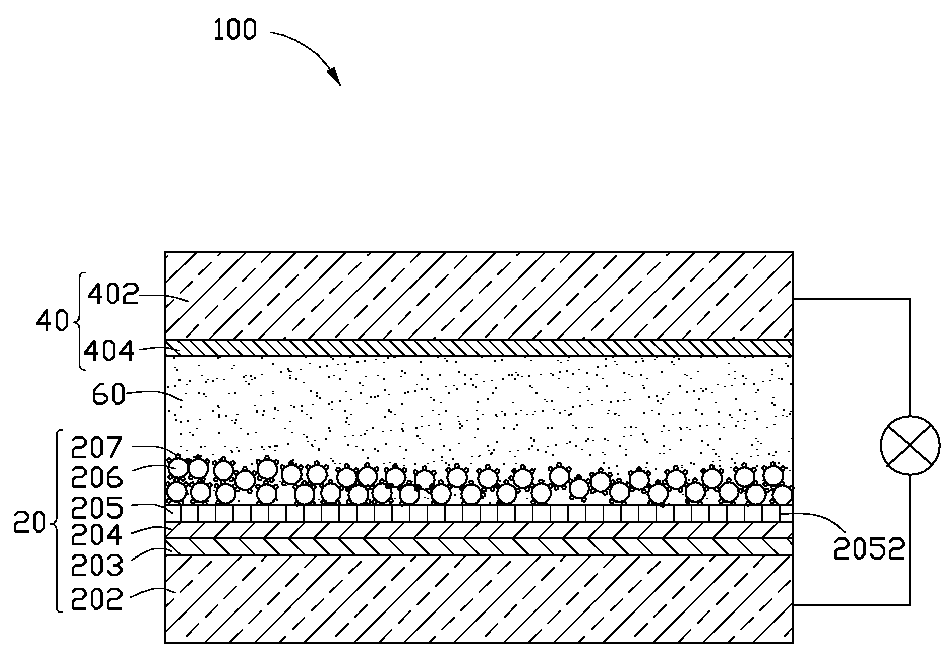
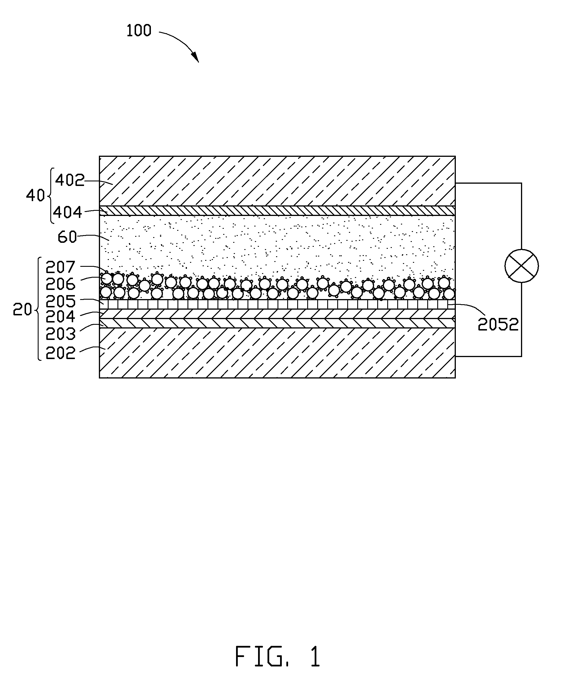
[0010]Referring to FIG. 1, a dye-sensitized solar cell 100 according to a present embodiment is shown. The dye-sensitized solar cell 100 includes a working electrode 20, a counter electrode 40, and a carrier transport layer 60.

[0011]The counter electrode 40 includes a transparent conductive substrate 402 and a metal layer 404 formed on the transparent conductive substrate 402. The transparent conductive substrate 402 can be a glass with a conductive oxide film formed on the glass. The metal layer 404 is formed on a surface of the counter electrode 40 facing the working electrode 20. The carrier transport layer 60 can be ion conductors such as a liquid electrolytic substance and an electrolytic polymer.

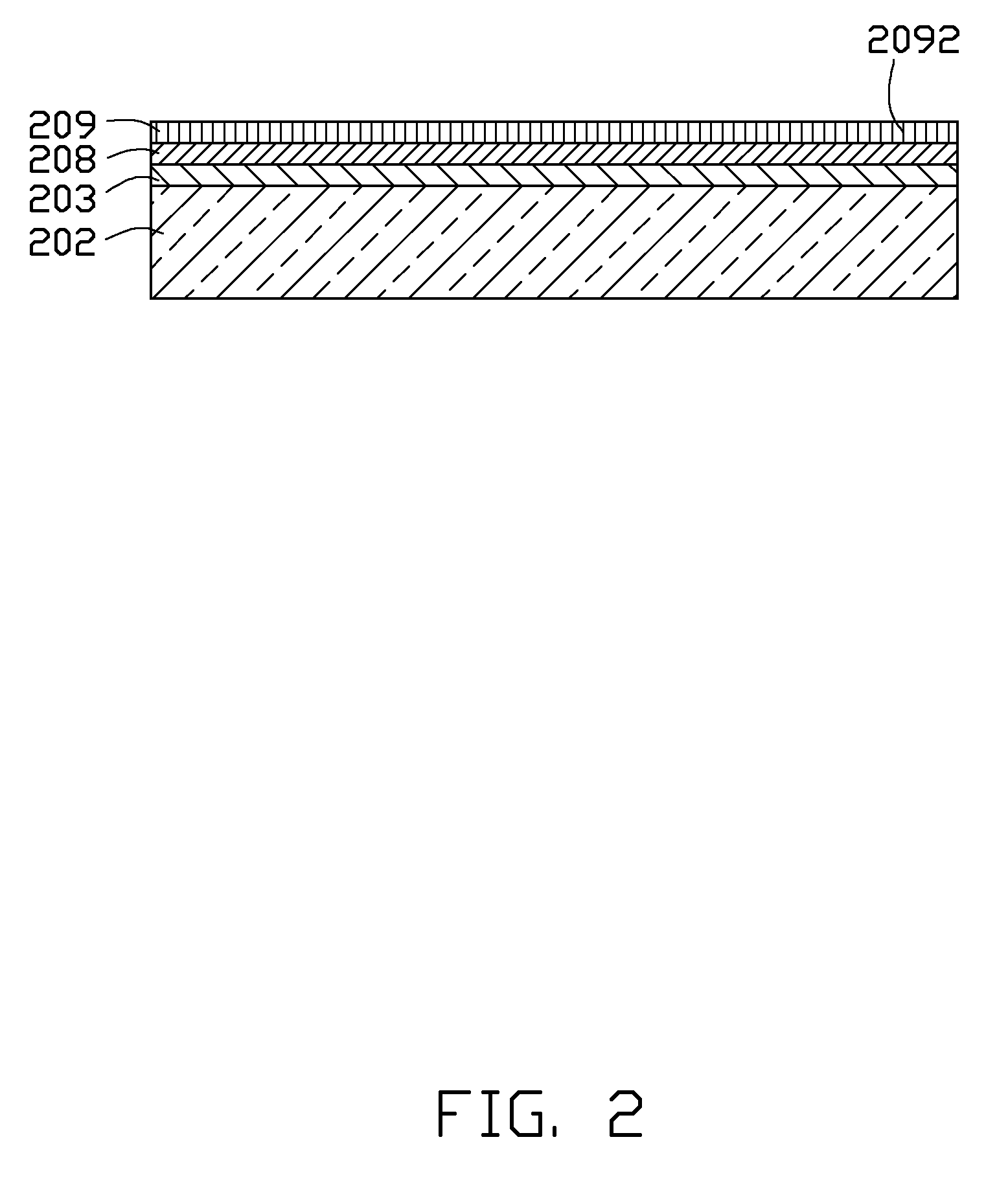
[0012]The working electrode 20 includes a transparent conductive substrate 202, a first metal layer 203 formed on the transparent conductive substrate 202, a metal oxide layer 204 formed on the first...


PUM

PropertyMeasurementUnit
transparentaaaaaaaaaa
transparent conductiveaaaaaaaaaa
semiconductoraaaaaaaaaa

Abstract

An exemplary working electrode includes a transparent conductive substrate, a nanorod layer formed on the transparent conductive substrate, and a porous semiconductor layer formed on the nanorod layer. The nanorod layer includes a plurality of nanorods. Each nanorod is comprised of a material selected from the group consisting of iridium-iridium oxide and ruthenium-ruthenium oxide. The porous semiconductor layer has a dye sensitizer adsorbed thereon.

Description

BACKGROUND[0001]1. Technical Field[0002]The present disclosure relates to a working electrode, a dye-sensitized solar cell having the working electrode and a method for making the working electrode.[0003]2. Description of Related Art[0004]A dye-sensitized solar cell is a relatively new class of low-cost solar cell, that belongs to the group of thin film solar cells. However, solar conversion efficiency of current dye-sensitized solar cell is not high enough.[0005]Therefore, what is needed, is a new dye-sensitized solar cell, which can overcome the above-mentioned problem.BRIEF DESCRIPTION OF THE DRAWINGS[0006]Many aspects of the embodiments can be better understood with references to the following drawings. The components in the drawings are not necessarily drawn to scale, the emphasis instead being placed upon clearly illustrating the principles of the present embodiments. Moreover, in the drawings, like reference numerals designate corresponding parts throughout the several views....

Claims


Application Information

Patent Timeline
Patent Type & Authority Applications(United States)
IPC IPC(8): H01L31/00H01L31/18
CPCH01G9/2031Y02E10/542H01G9/2059H01G9/2036Y02P70/50
Inventor PEI, SHAO-KAI
Owner HON HAI PRECISION IND CO LTD
Why Eureka
Try Eureka