
Heat sink module

a heat sink and module technology, applied in the direction of heat exchanger fastening, semiconductor devices of light sources, light and heating apparatus, etc., can solve the problems of low yield rate, high manufacturing cost, environmental contamination, etc., and achieve quick dissipation, quick dissipation of heat, and enhanced heat transfer efficiency

Active Publication Date: 2010-05-27
HUANG TSUNG HSIEN
View PDF3 Cites 39 Cited by
  • Summary
  • Abstract
  • Description
  • Claims
  • Application Information

AI Technical Summary

Benefits of technology

[0006]The present invention has been accomplished under the circumstances in view. The heat sink module of the present application comprises a heat transfer tube, a radiation fin set, and a heat transfer panel. The radiation fin set comprises a plurality of radiation fins that are radially riveted to the periphery of the heat transfer tube and then fastened to one another. The heat transfer panel is affixed to the bottom side of the heat transfer tube. During application, the heat transfer panel is kept in close contact with the heat source to transfer heat from the heat source to the radiation fins for quick dissipation.
[0007]The heat sink module is practical for use with a LED lamp to keep the heat transfer panel in direct contact with the light emitting unit of a series of light emitting diodes of the LED lamp for quick dissipation of heat from the light emitting diodes.
[0008]Further, each radiation fin comprises a plurality of retaining lugs at the top and bottom sides. By means of fastening the retaining lugs of one radiation fin to the retaining lugs of another radiation fin, the radiation fins are fastened together. Further, in a preferred embodiment, each radiation fin has its bottom retaining lugs arranged at different elevations to fit the stepped configuration of the heat transfer panel for direct contact, enhancing heat transfer efficiency.
[0009]According to still another aspect of the present invention, each radiation fin has its inner end ribbed into a ribbed end edge for quick fastening to one respective locating groove on the periphery of the heat transfer tube to increase the contact area between the heat transfer tube and the radiation fins for quick dissipation of heat.
[0010]According to still another aspect of the present invention, each radiation fin has its inner end ribbed into a ribbed end edge having a L-shaped, triangular, inverted T, or scrolled configuration for quick mounting in one respective locating groove on the periphery of the heat transfer tube to increase the contact area between the heat transfer tube and the radiation fins for quick dissipation of heat.
[0011]According to still another aspect of the present invention, the heat transfer tube can be directly extruded from a metal material by means of a metal extrusion process, thus simplifying the fabrication and lowering the heat transfer tube manufacturing cost.

Problems solved by technology

This heat sink module fabrication procedure is complicated, resulting in high manufacturing cost and low yield rate.
Further, nickel plating causes environmental contamination.
However, a LED projector lamp has low working temperature.

Method used


Image

  • Heat sink module
  • Heat sink module
  • Heat sink module

Examples


Embodiment Construction

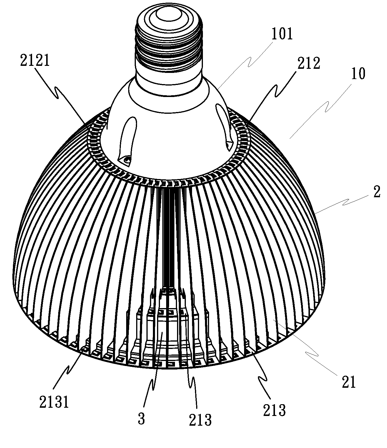
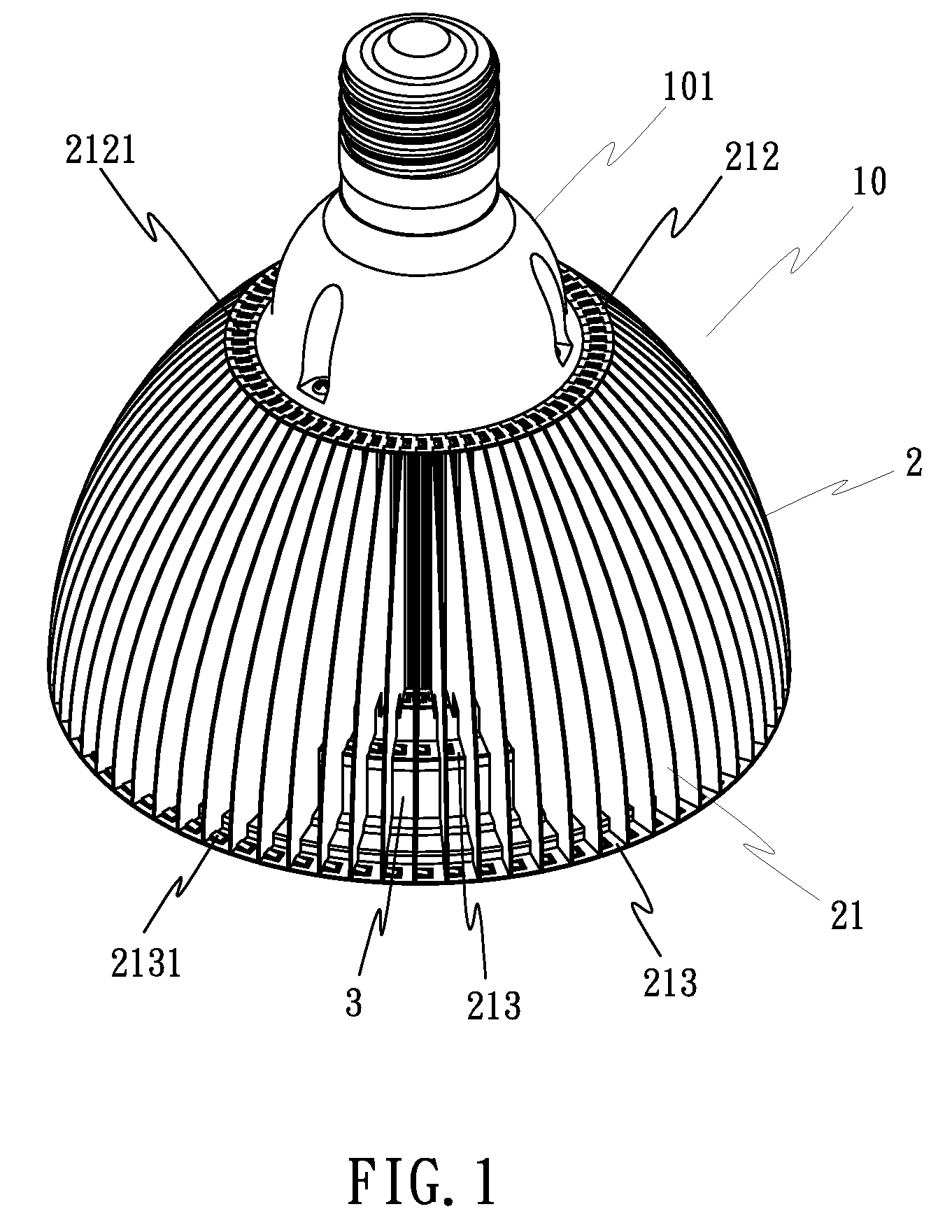
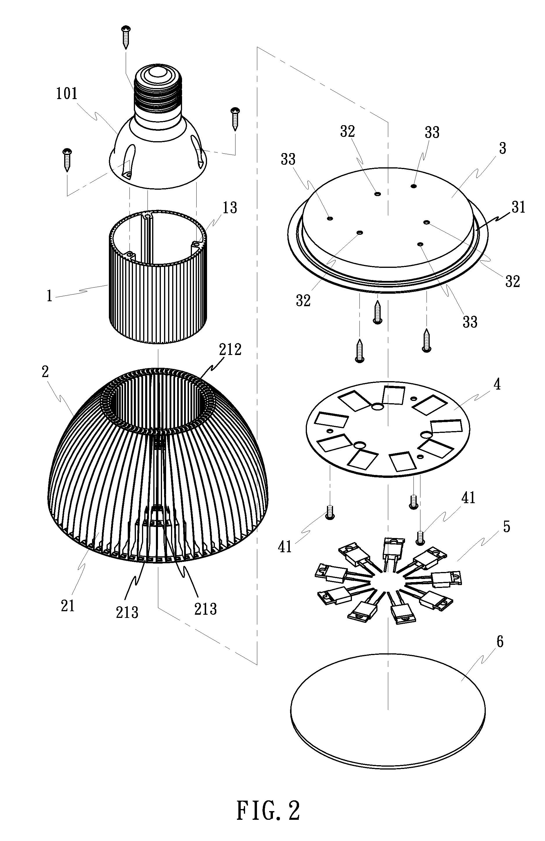
[0031]Referring to FIGS. 1˜3, a spherical heat sink module for a LED lamp 10 is shown. It is to be understood that the spherical heat sink module is applicable to other objects or in different fields. For example, the spherical heat sink module can be used to carry heat from a heat source in a computer (such as CPU). As illustrated, the spherical heat sink module comprises a heat transfer tube 1, a radiation fin set 2, and a heat transfer panel 3. These component parts can be made from copper, aluminum, or any of a variety of other heat conducting metals.

[0032]The heat transfer tube 1, as shown in FIGS. 2 and 4, a hollow tube having a plurality of locating grooves 11 and a plurality of V-grooves 12 alternately arranged around the periphery and longitudinally extending through the top and bottom ends, a plurality of mounting holes 13 equiangularly spaced around the inside wall. The locating grooves 11 are adapted to receive the radiation fins 21 of the radiation fin set 2 respectivel...


PUM


Abstract

A heat sink module includes a heat transfer tube, a plurality of radiation fins respectively riveted to locating grooves around the periphery of the heat transfer tube, and a heat transfer panel fastened to the bottom side of the heat transfer tube and the radiation fin set and kept in contact with a heat source, such as a CPU or a light emitting unit of a LED lamp for transferring heat from the heat source to the radiation fins for quick dissipation.

Description

BACKGROUND OF THE INVENTION[0001](a) Field of the Invention[0002]The present invention relates to heat sink technology and more particularly to a heat sink module, which comprises a heat transfer tube, a plurality of radiation fins radially arranged around the periphery of the heat transfer tube and fastened to one another, and a heat transfer panel affixed to the bottom side of the heat transfer tube for direct contact with a heat source to transfer heat to the radiation fins for quick dissipation.[0003](b) Description of the Prior Art[0004]Many heat sink modules are commercially available. A commonly used heat sink is comprised of a heat transfer base panel and a plurality of radiation fins arranged on the top side of the heat transfer base panel. The heat transfer base panel and the radiation fins are made from aluminum or copper. The radiation fins are bonded to the heat transfer base panel by means of heat fusion with a solder paste or bonding agent. If the heat transfer base p...

Claims


Application Information

Patent Timeline
Patent Type & Authority Applications(United States)
IPC IPC(8): F28F7/00
CPCF21Y2101/02F21Y2103/022F28F1/20F28F3/06F21V29/83F21V19/0055F21K9/137F21V29/71F21V29/773F28F2275/12F21V29/89F21K9/233F21Y2103/33F21Y2115/10
Inventor HUANG, TSUNG-HSIEN
Owner HUANG TSUNG HSIEN
Learn More