Adjustment mechanism for dish antenna system

Active Publication Date: 2010-05-27
DISH TECH L L C
View PDF1 Cites 9 Cited by
  • Summary
  • Abstract
  • Description
  • Claims
  • Application Information

AI Technical Summary

Benefits of technology

[0006]Some embodiments disclosed herein are generally directed to an adjustment mechanism for positioning an antenna. The adjustment mechanism includes a clip for coupling to a mast and for engaging a cam mechanism. The cam mechanism is operable to adjust the position of the an

Problems solved by technology

Conventional satellite dish antennas often have metal drive mechanisms that are relatively heavy and, thus, may contribute to fatigue problems, especially when the satellite dish antenna is exposed to cyclic loading, for example, during harsh weather conditions, such as during windstorms.
Metal components of the drive mechanism are often susceptible to corrosion and other types of dam

Method used


Image

  • Adjustment mechanism for dish antenna system
  • Adjustment mechanism for dish antenna system
  • Adjustment mechanism for dish antenna system

Examples


Embodiment Construction

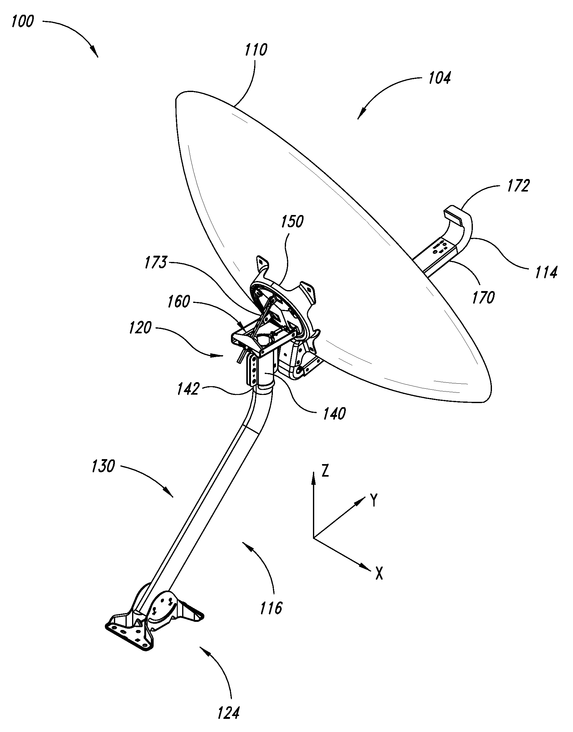
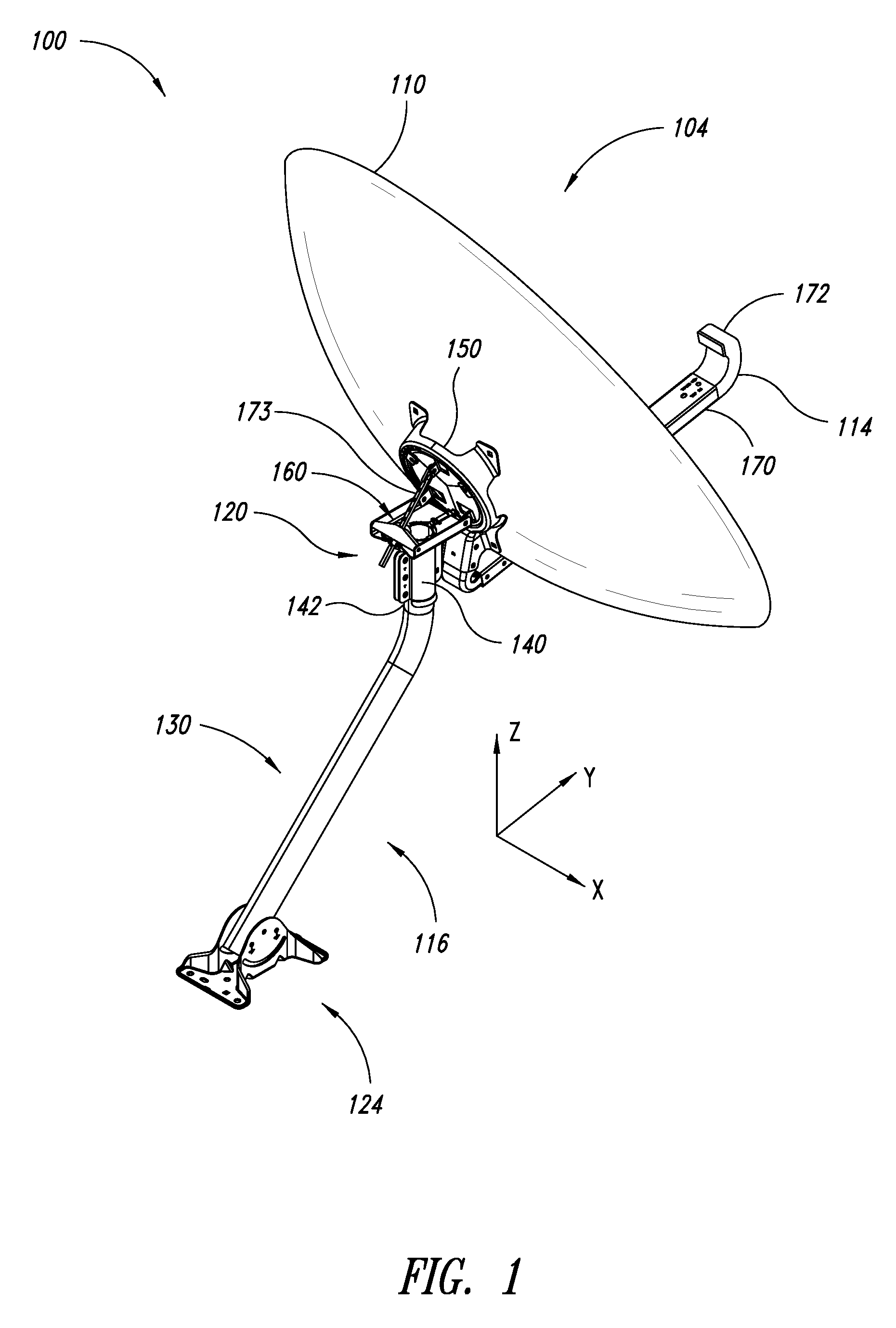
[0026]FIG. 1 shows an antenna system 100 that includes a dish antenna 104 and a support assembly 116 supporting the dish antenna 104. The dish antenna 104 includes a dish 110 and a waveguide 114, illustrated as a feedhorn, positioned to communicate with the dish 110. The support assembly 116 includes a bracket mechanism 120, an anchoring bracket 124, and a mast 130 extending between the bracket mechanism 120 and the anchoring bracket 124. The bracket mechanism 120 connects the mast 130 to the dish antenna 104. The illustrated bracket mechanism 120 includes a mast mounting portion 140 coupled to an upper end 142 of the mast 130 and an antenna mounting portion 150 supporting the dish antenna 104. The antenna mounting portion 150 is rotatably coupled to the mast mounting portion 140 to adjust elevation settings.

[0027]The dish 110 is configured to transmit signals to and / or receive signals from one or more communication systems, such as one or more satellites. The dish 110 can be a circ...


PUM


Abstract

Antenna systems include adjustment mechanisms to adjust the position of dish antennas. The adjustment mechanism includes a clip, a bracket, and a cam mechanism. The clip is fixedly coupled to and projects outwardly from a mast. The bracket is pivotally coupled to the mast and is between the stationary clip and cam mechanism. The cam mechanism is pivotally coupled to the clip and positioned to rotate the bracket and the dish antenna as the cam mechanism rotates. The clip is made of a lightweight material to reduce the overall weight of the antenna system to enhance performance.

Description

BACKGROUND[0001]1. Technical Field[0002]The present disclosure generally relates to adjustment mechanisms for antennas and, more particularly, to adjustment mechanisms for dish antenna systems.[0003]2. Description of the Related Art[0004]Satellite dish antennas are commonly used in television receiving systems. A satellite dish antenna often has a dish-shaped receiver that collects and focuses incoming transmissions transmitted by a satellite. A parabolic surface of the dish-shaped receiver can reflect the transmissions to a waveguide, such as a feedhorn. Satellite dish antennas can be mounted on roofs, walls, residential structures, commercial buildings, or the like.[0005]Satellite dish antennas can be highly directional antennas that are aimed at a desired broadcasting satellite in order to properly receive a transmission. There should be a clear line of sight between the satellite dish antenna and the satellite. Aiming is generally performed by adjusting an azimuth angle and an e...

Claims


Application Information

Patent Timeline
IPC IPC(8): H01Q3/02
CPCH01Q1/1264H01Q19/132H01Q19/13H01Q3/04
Inventor FRUH, JASON MATTHEWKIRBY, MORGAN HADEN
Owner DISH TECH L L C
Why Eureka
Try Eureka