[0006]In accordance with embodiments of the subject invention, proper compressor lubrication and operation is achieved by lubricating oil entrained in the
working fluid vapor entering the compressor. Preferred embodiments can achieve proper compression lubrication without an
oil separation mechanism and without the need for an oil
sump to collect the separated oil. In accordance with embodiments of the subject invention, the oil-vapor mixture remains as a mixture upon entering and exiting the compressor within a flow path that does not allow significant amounts of, if any, oil to collect, so as to reduce the
mass flow rate of oil entrained in the
working fluid entering the compressor in a way so as to not adequately lubricate the compressor independent of the orientation of the compressor, with respect to the surrounding
gravitational field.
[0007]The oil-vapor flow path can be achieved by actively minimizing the internal volumes of the compressor that can potentially fill with separated oil. When oil fills into such internal volumes, the oil loses contact with the working fluid due to the localized reduction in vapor velocity through the internal volume of flow path such that the oil in such internal volumes does not remain entrained with the working fluid vapor. By reducing the amount of internal volume that
oil can reside so as to avoid the forces of the moving working fluid vapor, enough of the oil by volume is circulated in the working fluid though the vapor compression cycle and entrained in the flow path for the working fluid vapor and oil mixture at the compressor inlet and outlet, such that proper compressor lubrication can be achieved. In specific embodiments, more than 70%, more than 80%, and more than 90%, respectively, of the oil by volume is circulated in the working fluid through the vapor compression cycle and entrained in the flow path for the working fluid vapor, independent of the orientation of the compressor with respect to the surrounding
gravitational field. In further embodiments, the amount of the lubricating oil entrained in the working fluid vapor, or oil
mass flow rate, at any orientation of the compressor with respect to the surrounding
gravitational field is at least 80%, at least 90%, and at least 95%, respectively, of the maximum amount of the lubricating oil entrained in the working fluid vapor, or maximum oil
mass flow rate, where the maximum amount of the lubricating oil entrained in the working fluid, or maximum oil mass flow rate vapor is achieved at one or more orientations of the compressor, or vapor compression cycle
system, that results in a maximum mass flow rate of lubricating oil being entrained in the working fluid vapor. In this way, the mass flow rate of oil entrained remains within a certain range of a maximum mass flow rate of oil, based on the mass flow rate of oil in the compressor, or vapor compression cycle system, and the design of the compressor, or vapor compression cycle system, respectively.
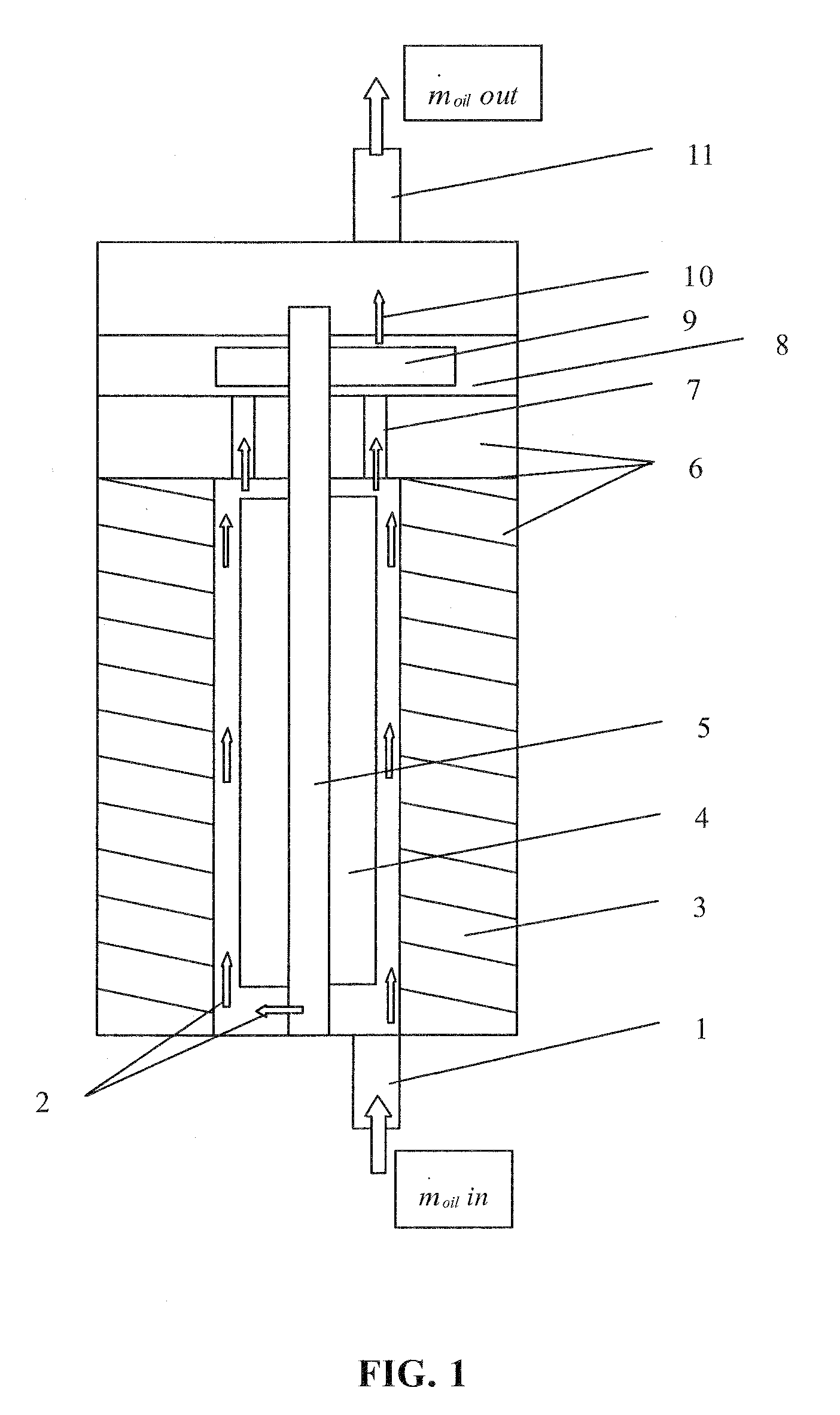
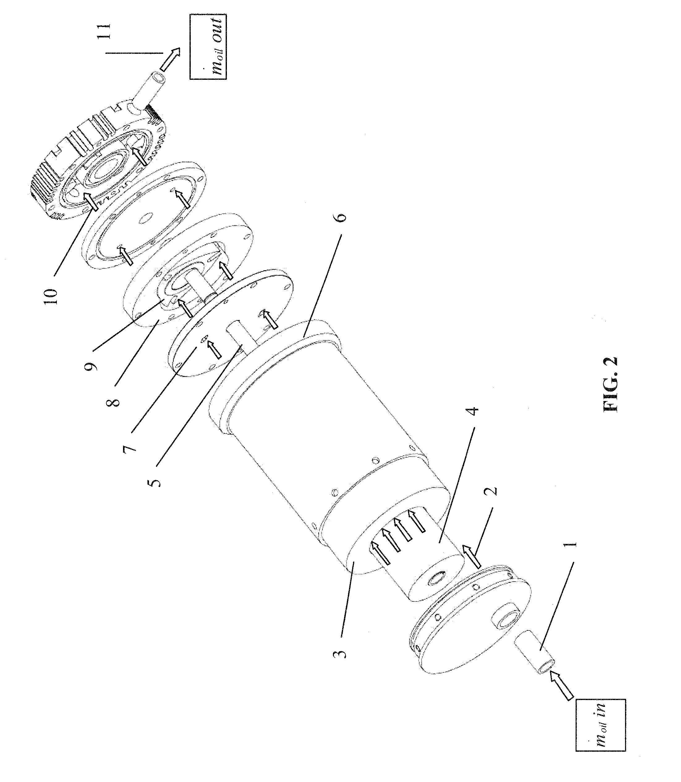
[0009]In order to maintain an adequate oil-vapor mixture velocity, compressor internal volumes, often unavoidable during manufacture and compressor
assembly, can be partially, or completely, filled. Internal volumes that can cause oil to be removed from the flow can be minimized, when possible, prior to manufacture. Empty volumes inside the compressor can be avoided during construction of the compressor and flow path, or can be filled with various filler materials, such as metals, epoxies, plastics, and rubbers once construction is complete. With few, if any, empty volumes or pockets for the oil to collect, the oil remains mixed with the
refrigerant vapor as it travels to and from the compressor, and results in an oil mass flow balance across the compressor and the entire vapor compression cycle. The mass flow rate of oil that enters the compressor is equivalent to the mass flow rate of oil that exits the compressor and requires no
oil separation mechanism.
[0010]In further embodiments, the flow path of the working fluid and oil outputted from the compressor into a vapor compression cycle system can be designed using the same techniques previously mentioned to reduce or eliminate empty spaces that can gather oil in a way that would
impact the oil entrained in the working fluid entering the compressor. Preferably, the mass flow rate of oil that exits the compressor flows through the flow path and enters the compressor independent of the orientation to the surrounding gravitational field. In a specific embodiment, the mass flow rate of oil that enters the rest of the vapor
compression system from the output port of the compressor is equal to the mass flow rate of oil that enters the input port of the compressor from the vapor
compression system and the vapor compression system does not include any means of active
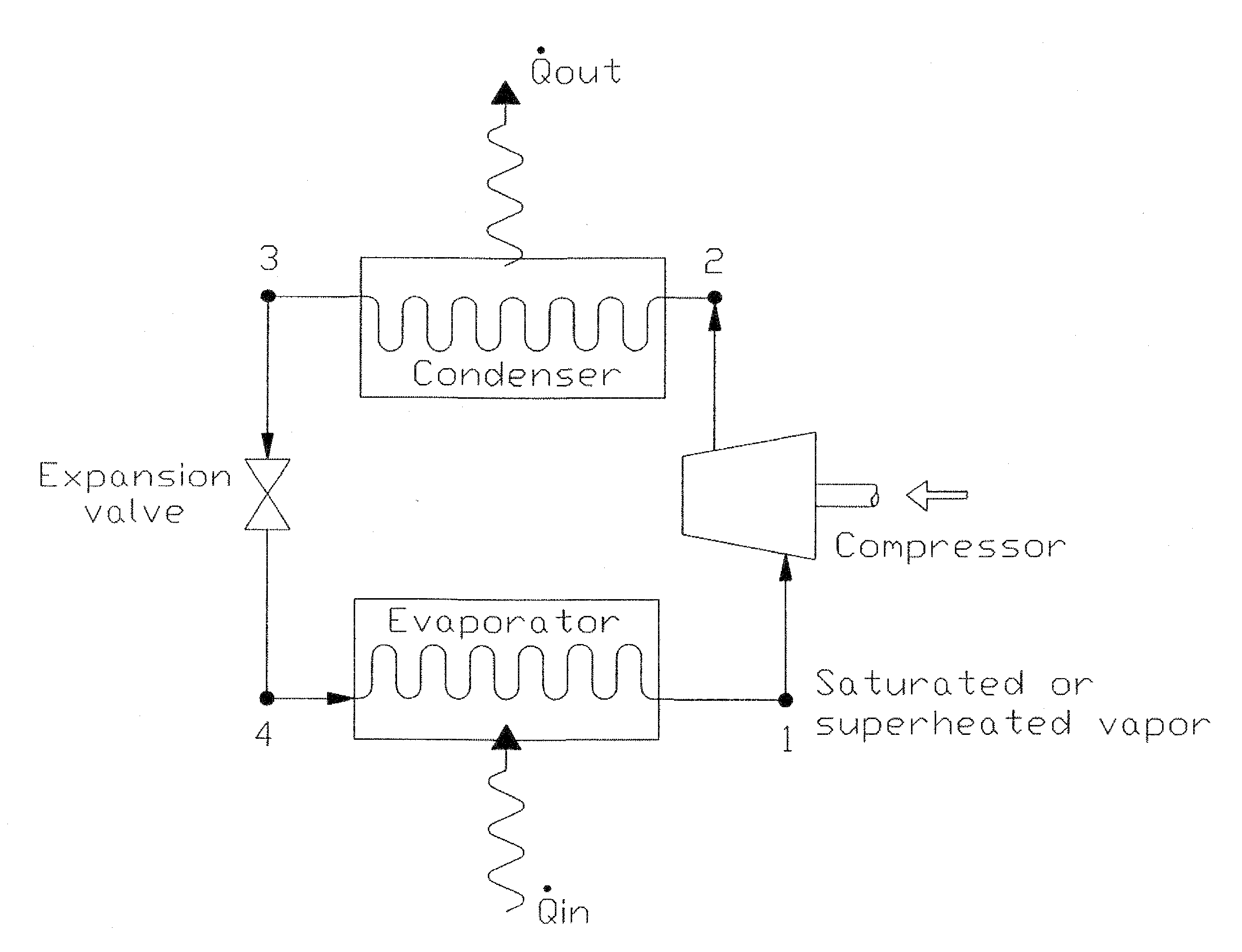
oil separation, thus enabling gravitational independence. In this way, oil does not build up in internal volumes connected to the flow path when the vapor compression cycle system is in a first orientation, so as to be removed from the flow through the flow path, and then release back into the flow path when the orientation of the vapor compression cycle system is changed to a second orientation. After compression, the oil-vapor mixture is then directed to the next component in the vapor compression cycle. Components of a vapor compression cycle system can include, for example, a condenser, an expansion device, an
evaporator, one or more filters, one or more receivers, one or more accumulators, one or more by-pass valves, and one or more
interconnection tubes or other
interconnection apparatus. In a specific embodiment, the working fluid and oil are outputted by the compressor, pass through a condenser, then pass through an expansion device, and finally pass through an
evaporator before being inputted back into the compressor.
[0011]Embodiments of the subject invention can enable proper compressor operation largely, or completely, independent of compressor orientation with respect to the
gravitation field. Orientation independence is accomplished by maintaining adequate oil lubrication in many, if not all, possible geometric orientations by removing the oil separation mechanisms, oil sumps, oil bypass and bleed lines, and other means of oil separation incorporated in conventional compressors. With embodiments of the subject invention, the oil and vapor remain mixed through the implementation of a clearly defined oil-vapor flow path by
filling in, reducing, and / or eliminating, empty volumes for oil collection to occur. Removing the oil separation mechanisms that are gravity dependent allows proper compressor operation independent of the compressors orientation, whether vertical, horizontal, or in any other orientation angle.

