Spherical Filling Body

Active Publication Date: 2010-06-03
STELZL THOMAS KURT
View PDF30 Cites 7 Cited by
  • Summary
  • Abstract
  • Description
  • Claims
  • Application Information

AI Technical Summary

Problems solved by technology

Yet, practice has shown that splinter wastes and abrasion particles are caused when cutting with cutter drums which are considerably detrimental to the applications according to these patents.
Afterwards, the material which has accordingly been provided with longitudinal cuts will be stretched, involving the serious drawback that the material web provided with the longitudinal cuts must be stretched by pulling the web apart in the width direction, thus causing a widening of the web and, at the same time, a shortening of the web in the running direction.
The use of bale-type stretched metals as explosion-protection means is that the containers are filled with a block of stretched metal whose dimensions do not correspond to the internal dimensions of the container and can thus not be removed from the container or in a very difficult fashion by destroying the block.
Moreover, this technology involves the substantial drawback that the containers cannot be filled later on via small openings (e.g. fill-in nozzles).
Yet, practice has shown that no perfect result can be achieved by any of these production methods since the filling bodies which are always produced from stretched metal are no spheres but at the best spherical compressed bodies whose tendency to get stucked by jamming of the upward-turned or pressed gap rims of the stretched metals can at least not fully be excluded with the reliability necessary.
This is why these spheres do not reliably roll on each other and one can consequently never be sure whether the spheres reliably fill the container to be protected completely.
This bears a considerable risk since there must not remain any cavities inside of the tank so as to provide for proper explosion protection.
Furthermore, in particular aluminum filling bodies tend to strong abrasion with respect to each other due to their rubbing contact when they have been introduced into a container.
Moreover, it has proven that these spherical compressed bodies of pressed and shaped stretched metal do in no case permanently have the shape stability or strength necessary against gas or liquid-pressure peaks so that the spheres filled into gasoline tanks will nest after longer periods of use, and the tank is thus no longer entirely filled up to an extent necessary for explosion protection.
Furthermore, these filling bodies are unstable so that filling into the tank by means of a blow-in device, and in particular sucking the filling bodies off the tank may produce damage to the filling bodies and deform the same.
In general, the substantial disadvantage of filling bodies made of expanded metal however is that they are produced according to the respective method by compressing, and shaping, stretched metal, wherein this principle of production does not allow for the geometrical properties (precise displacement, volumes, etc.) of the produced filling bodies to be defined by calculation in a precise and binding manner.
Particularly the fact that the filling bodies made of expanded metal and produced according to the above methods have a not insignificant flow resistance leads to serious disadvantages as regards their ability of being flown-through by liquids or gases.
In general, the entire method in which expanded metal is used in the form of network-type bales and in the form of filling bodies made of these networks involves the further substantial drawback that the applied physical principle of surface increase and / or flame cooling tends to prevent only an explosion but does not prevent a fire or provide for extinguishing of the same.

Method used


Image

  • Spherical Filling Body
  • Spherical Filling Body
  • Spherical Filling Body

Examples


Embodiment Construction

[0011]The object is achieved by the filling body set forth in the claims. An advantage of the filling body described is that it has the spherical shape with an absolutely smooth surface which is ideal for the methods defined in the claims, and the filling bodies described roll on each other perfectly and fill a container completely with the most possible reliability. There will definitely not be any bridge formation by jamming of the filling bodies described. The production methods described in the claims allow for the properties of the described filling body to be precisely adapted to the respective purpose of use, and for identity of all filling bodies. A further advantage of the described filling body is that is has as low a volume displacement and weight as possible. Although the containers must be completely filled with the inventive filling bodies, the described filling bodies must have such a high portion of cavities that the capacity for the liquid contents of the container ...


PUM

PropertyMeasurementUnit
Temperatureaaaaaaaaaa
Lengthaaaaaaaaaa
Pressureaaaaaaaaaa

Abstract

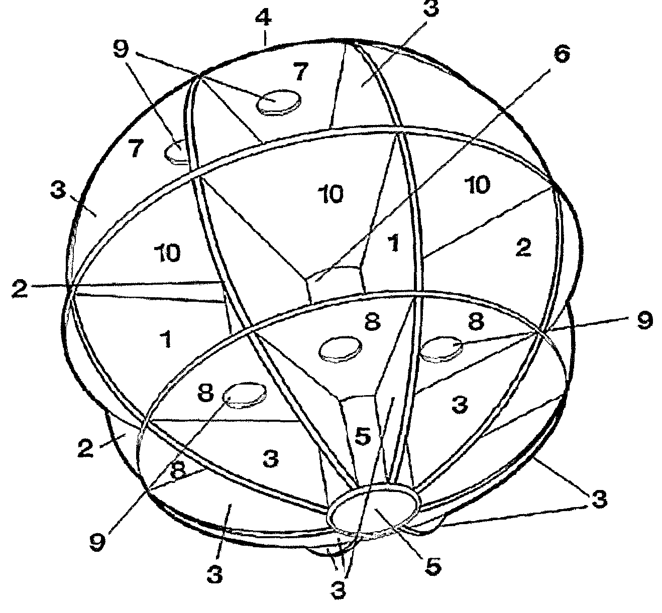
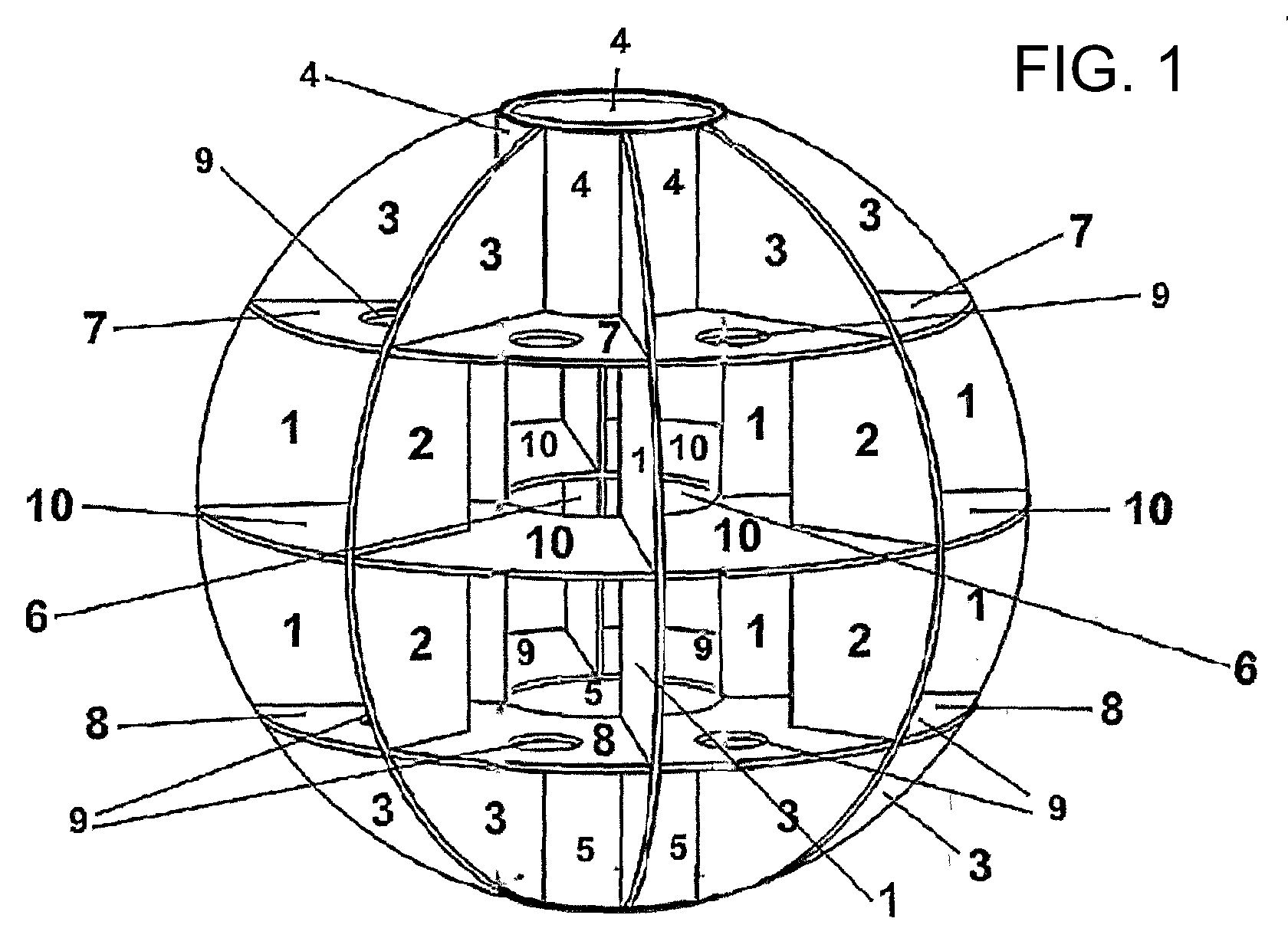
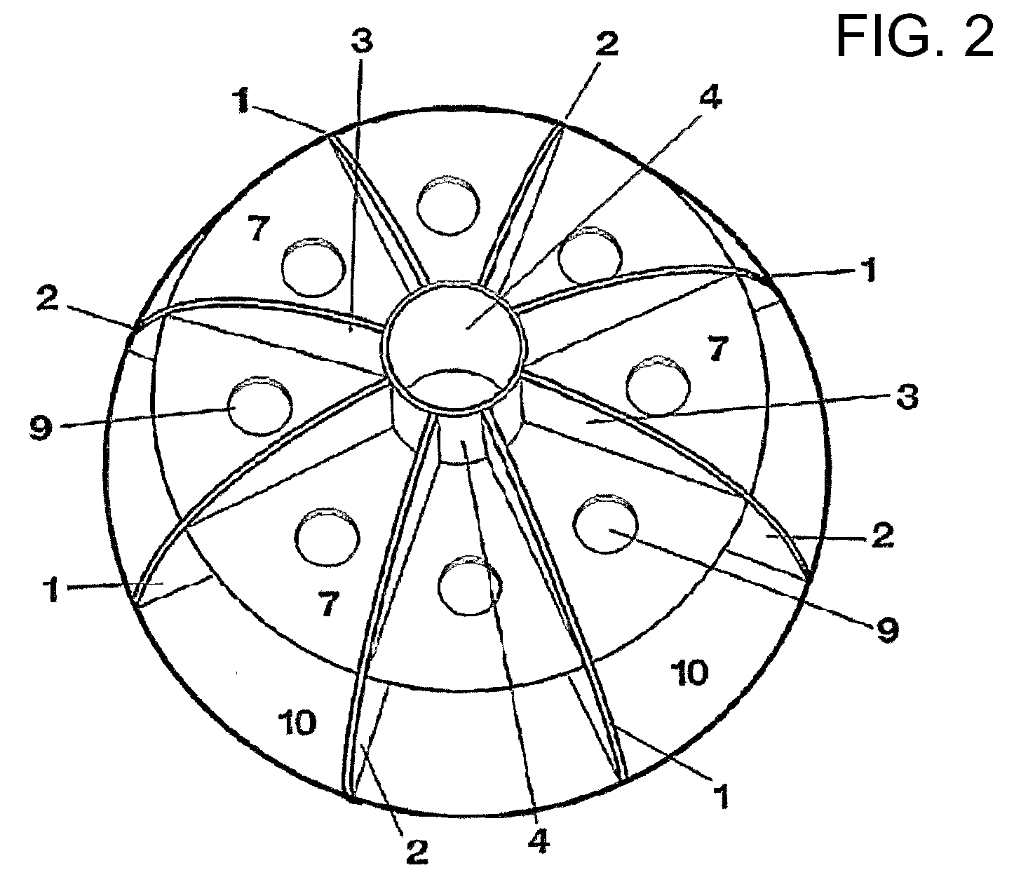
The invention relates to the production of a spherical, hollow filling body for filling containers for flammable and inflammable liquids or gases, as well as to methods for its particularly advantageous uses, e.g. for preventing explosion-type burning processes and explosions, for extinguishing fires, as a corrosion protection in tank containers, for separation of fuels and water, as a protection against bacteria and fungi in fuel tanks, as an anti-theft protection, for reducing carbon-hydrogen emissions, for increasing stability and crash safety of tank containers, for reducing the boil-off effect of hydrogen, for applications in chemical industry, for dissipating static electricity from fuel containers, for protecting against electromagnetic disturbances, for reducing and delaying the BLEVE effect, for increasing the filling capacity of gas containers, for heating and cooling liquids and gases, as well as for reducing the vaporization loss. Furthermore, the invention relates to methods of producing the filling bodies. FIG. 1 shows an inventive spherical filling body which consists of several disk-shaped, circular vertical surfaces 1, 2 and 3, and of disk-shaped, circular, parallel horizontal surfaces 7, 8 and 10. In the center of the horizontal surface 10, there is a circular opening 6 which, together with the inwardly-open circular upper sleeve-shaped body 4 and the inwardly-open circular bottom sleeve-shaped body 5, forms an axially-continuous, tubing 30 from top 4 to bottom 5, wherein the inside diameter of the sleeve-shaped and inwardly-open, circular bodies 4, 5 and of the circular opening 6 are identical. The vertical surfaces 1 extend from the outer edge of the spherical body to the edge of the respective circular through holes 4, 5 and 6 of the parallel horizontal surfaces 7, and 8 surrounding the through-holes. The vertical surfaces 2 extend from the outer edge of the spherical body as far as to half the distance between the outer edge of the spherical body on the horizontal surfaces 8 and 10, and between the edge of the circular through-holes 5 and 6 of the horizontal surfaces. The vertical surfaces 3, on the top 4 and on the bottom 5, form the connection between the horizontal surfaces 7 and 8 and the sleeve-shaped bodies 4 and 5. Openings 9 are provided in the horizontal surfaces 8 and 7. These are arranged such that one opening 9 is provided in the horizontal surface 8 between the vertical surfaces 1 and 2, and one opening 9 is provided in the horizontal surface 7 between the vertical surfaces 3.

Description

[0001]The invention relates to an article in the form of spherical, hollow filling bodies for filling containers for flammable and inflammable liquids or gases, as well as to methods to its particularly advantageous uses, e.g. for preventing explosion-type deflagrating processes and explosions, for extinguishing fires, as a corrosion protection in tank containers, for separation of fuels and water, as a protection against bacteria and fungi in fuel tanks, as an anti-theft protection, for reducing carbon-hydrogen emissions, for increasing stability and crash safety of tank containers, for reducing the boil-off effect of hydrogen, for applications in chemical industry, for dissipating static electricity from fuel containers, for protecting against electromagnetic disturbances, for reducing and decelerating the BLEVE effect, for increasing the filling capacity of gas containers, for heating and cooling liquids and gases, as well as for reducing the vaporization loss.[0002]Furthermore, ...

Claims


Application Information

Patent Timeline
IPC IPC(8): B65B1/04A62C3/00A62C2/00F17D3/00
CPCA62C3/06B60K15/077Y02E60/34F17C2260/016Y02E60/321B60K2015/03381Y10T137/0318Y02E60/32
Inventor STELZL, THOMAS KURT
Owner STELZL THOMAS KURT
Why Eureka
Try Eureka