Welding method of girth weld of inner cladding thin-walled stainless steel composite tube

A welding method and technology for composite pipes, which are applied in welding equipment, welding equipment, welding accessories, etc., can solve the problems of melting of base metal, affecting corrosion resistance of clad welds, and poor matching of mechanical properties of welded joints. Achieve the effect of solving the decline of corrosion resistance and overcoming adverse effects

Inactive Publication Date: 2010-01-27
XI AN JIAOTONG UNIV
View PDF3 Cites 58 Cited by
  • Summary
  • Abstract
  • Description
  • Claims
  • Application Information

AI Technical Summary

Problems solved by technology

[0004] The Chinese patent authorization number is CN1267234C. There are two disadvantages in the patent: one is that the cladding layer and the transition layer use the same welding material. The difference between the multi-layer joints affects the corrosion resistance of the multi-layer joints; the second is that the transition layer welds are easy to be welded on the pipe base, multi-layer, and transition layers due to the sparse effect of the base carbon steel layer and the mechanical combination between the pipeline multi-layer and the base layer. Defects such as cracks and pores at the seam joint
[0005] Chinese Patent Publication No. is the shortcoming that the patent application of CN101100013A exists has three points: the one, although can solve the pore defect problem that the slit between cladding layer and the basic layer interface brings better by sealing welding, but can not solve the pore defect problem that slit exists. The second is the welding of the sealing weld bead and the welding of the multi-layer. The two welding increases the width of the multi-layer weld and the number of times of heating, which will seriously affect the corrosion resistance of the multi-layer weld; the third is the entire girth welding The welding of seams is all made of stainless steel welding materials that match the clad stainless steel. The adjustability of the mechanical properties of the welded joints is relatively poor, resulting in poor matching of the mechanical properties of the entire welded joints. At the same time, it is easy to form between the base weld and the base. Transitionally hardened layer, resulting in deterioration of the performance of the heat-affected zone of the base layer
[0006] Chinese Patent Publication No. is that the shortcoming of the patent application of CN13454061A has three points: the one, because the thermal effect of multilayer welding, produces thermal shrinkage, easily causes the separation between the multilayer and the base layer to produce gap, and is easy to form crack when the transition layer is welded, The second is the groove form adopted in the patent application. During the multi-layer welding, it is inevitable that the base metal will melt and enter the multi-layer weld, which will affect the chemical composition of the multi-layer weld, resulting in the multi-layer weld resistance. Third, the groove form adopted in the patent application results in poor accessibility of the argon arc welding torch during multi-layer welding

Method used


Image

  • Welding method of girth weld of inner cladding thin-walled stainless steel composite tube
  • Welding method of girth weld of inner cladding thin-walled stainless steel composite tube
  • Welding method of girth weld of inner cladding thin-walled stainless steel composite tube

Examples


Embodiment 1

[0036] The girth welding of SAF 2205 duplex stainless steel / Q235 carbon steel composite pipe is taken as an example to describe this embodiment. The cladding 2 of the composite pipe is duplex stainless steel SAF 2205 with a thickness of 2 mm; the base layer 1 is carbon steel Q235 with a thickness of 12 mm. The welding of this composite pipe adopts the following steps:

[0037] (1) Groove processing

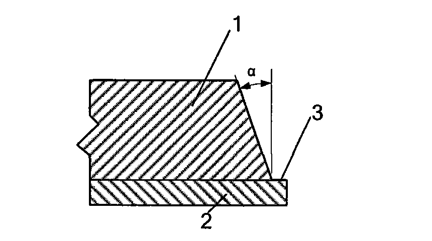
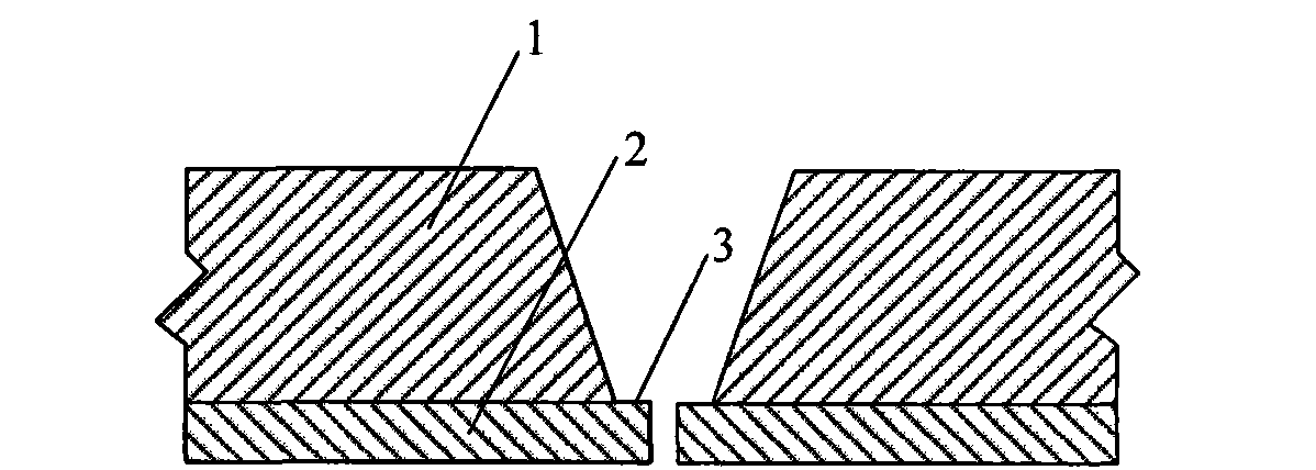
[0038] according to figure 1 , the bevel processing is carried out on the base layer 1 of the composite pipe end, wherein the unilateral bevel angle α is 20°, so that the pipe end coating 2 protrudes from the base layer 1, and the extension width 3 of the coating is 2mm, and the thickness of the blunt edge is the same as The cladding thickness is the same (thickness of blunt edge is figure 2 The cladding 2 thickness shown in, one of the characteristics of the present invention is that the thickness of the blunt edge is the same as the thickness of the cladding, that is to say,...

Embodiment 2

[0052] Taking 0Cr18Ni9 austenitic stainless steel / 16Mn low-alloy steel composite pipe girth welding as an example, the embodiment of the present invention is described. The cladding 2 of the composite pipe is 0Cr18Ni9 austenitic stainless steel with a thickness of 1.5 mm; the base layer 1 is low alloy steel Q345 with a thickness of 8 mm. The welding of this composite pipe adopts the following steps:

[0053] (1) Groove processing

[0054] according to figure 1 , carry out groove processing on the base layer 1 of the pipe end of the composite pipe, wherein the single-side groove angle α is 15°, so that the pipe end coating 2 protrudes from the base layer 1, and the coating extension width 3 is 1.5mm, and the thickness of the blunt edge Same as cladding thickness (thickness of blunt edge is figure 2 The cladding 2 thickness shown in, one of the characteristics of the present invention is that the thickness of the blunt edge is the same as the thickness of the cladding, that ...

Embodiment 3

[0064] Taking SAF 2205 duplex stainless steel / 15CrMo low-alloy steel composite pipe girth welding as an example, the embodiment of the present invention will be described. The cladding 2 of the composite pipe is duplex stainless steel SAF 2205 with a thickness of 3 mm; the base layer 1 is low alloy steel 15CrMo with a thickness of 20 mm. The welding of this composite pipe adopts the following steps:

[0065] (1) Groove processing

[0066] according to figure 1 , carry out groove processing on the base layer 1 of the composite pipe end, wherein the single-side groove angle α is 25°, so that the pipe end coating 2 protrudes from the base layer 1, and the coating extension width 3 is 3.5 mm, and the blunt edge thickness Same as cladding thickness (thickness of blunt edge is figure 2 The cladding 2 thickness shown in, one of the characteristics of the present invention is that the thickness of the blunt edge is the same as the thickness of the cladding, that is to say, the cla...


PUM

PropertyMeasurementUnit
thicknessaaaaaaaaaa
thicknessaaaaaaaaaa
thicknessaaaaaaaaaa

Abstract

The invention relates to a welding method of a girth weld of an inner cladding thin-walled stainless steel composite tube. The welding method comprises the following steps: girth welds of the inner cladding stainless steel composite tube are respectively and gradually welded by three welding seams, an inner cladding layer welding seam and a transition layer welding seam are welded by argon tungsten-arc welding, the stainless steel inner cladding layer welding seam adopts welding wires with the same quality thereof, the transition layer welding seam adopts ER309 welding wires, and the base layer is welded by shielded metal arc welding or CO2 gas shielded welding and adopts a welding material matched with the strength of the base layer; and the inner cladding layer, the transition layer and the first layer of the base layer are welded under back argon gas protection. The welding method guarantees corrosion resistance of a joint of the inner cladding layer and mechanical property of a welding joint of the base layer; and the method plays an important role in promoting wide application of the inner cladding stainless steel composite tube in businesses such as oil-gas delivery, chemical industry, oil refining and the like, improving corrosion resistance of an inner wall of a pipe, and solving the problems of high cost and the like caused by adopting a full wall-thickness stainless steel pipe.

Description

technical field [0001] The invention belongs to the field of metal material welding, and relates to a method for welding a girth weld of a bimetal composite pipe, in particular to a method for welding a girth weld of an inner-covered thin-walled stainless steel composite pipe. Background technique [0002] Inner clad stainless steel composite pipes are widely used in oil and gas transportation, chemical and oil refining industries, and can effectively solve the problems of corrosion of the inner wall of the pipeline and high cost caused by the use of full-wall stainless steel pipes. At the same time, the inner clad stainless steel composite pipe also has the characteristics of strong base layer adjustability. According to the mechanical performance requirements of the pipeline, metal materials with different strength and toughness can be selected as the base material to meet the mechanical performance requirements of the composite pipe. Due to the low cost, corrosion resista...

Claims


Application Information

Patent Timeline
Patent Type & Authority Applications(China)
IPC IPC(8): B23K9/23B23K9/028B23K9/235B23K33/00B23K9/32B23K9/167B23K9/095B23K37/053
Inventor 牛靖张建勋毕宗岳张峰朱彤付强
Owner XI AN JIAOTONG UNIV
Why Eureka
Try Eureka