Detecting electrical current in a magnetic structure

a magnetic structure and detection technology, applied in seismology, instruments, waterlogging using reradiation, etc., can solve problems such as electromagnetic data distortion

Active Publication Date: 2010-06-03
SCHLUMBERGER TECH CORP
View PDF6 Cites 32 Cited by
  • Summary
  • Abstract
  • Description
  • Claims
  • Application Information

AI Technical Summary

Benefits of technology

[0005]A current sensor measures an electrical current flowing in a casing or other magnetic structure. The current sensor can be installed in a tool for performing electromagnetic (EM) induction surveying in a wellbore lined with an electrically conductive and magnetic casing. The tool includes an EM element to transmit or receive a magnetic field through the casing. The current measurement may be used to correct for a change in casing effect on the EM element.

Problems solved by technology

As a result, currents induced into casing may cause data distortion of electromagnetic induction surveying using receivers positioned in steel cased wellbores.

Method used


Image

  • Detecting electrical current in a magnetic structure
  • Detecting electrical current in a magnetic structure
  • Detecting electrical current in a magnetic structure

Examples


Embodiment Construction

[0016]In the following description, numerous details are set forth to provide an understanding of the present invention. However, it will be understood by those skilled in the art that the present invention may be practiced without these details and that numerous variations or modifications from the described embodiments are possible.

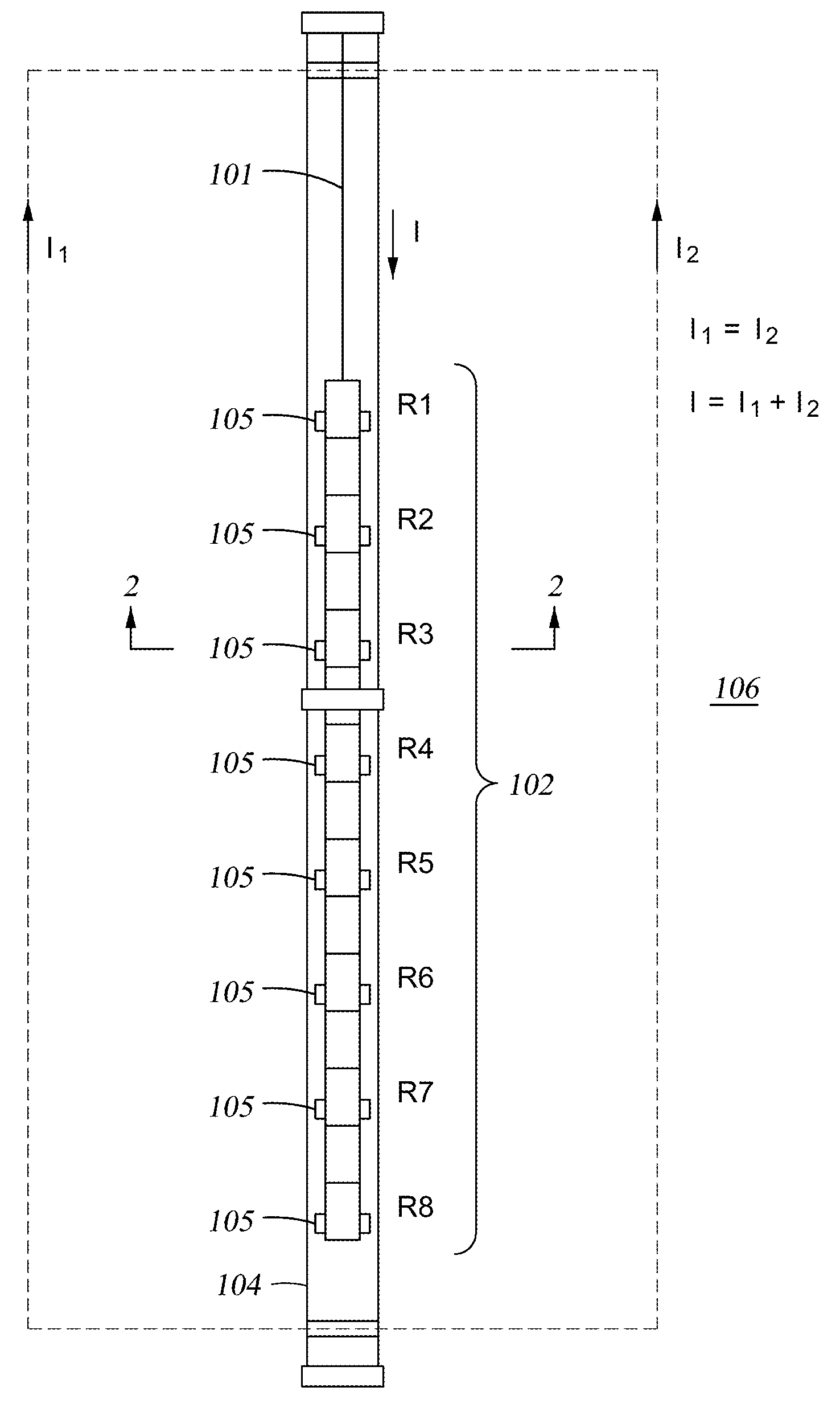
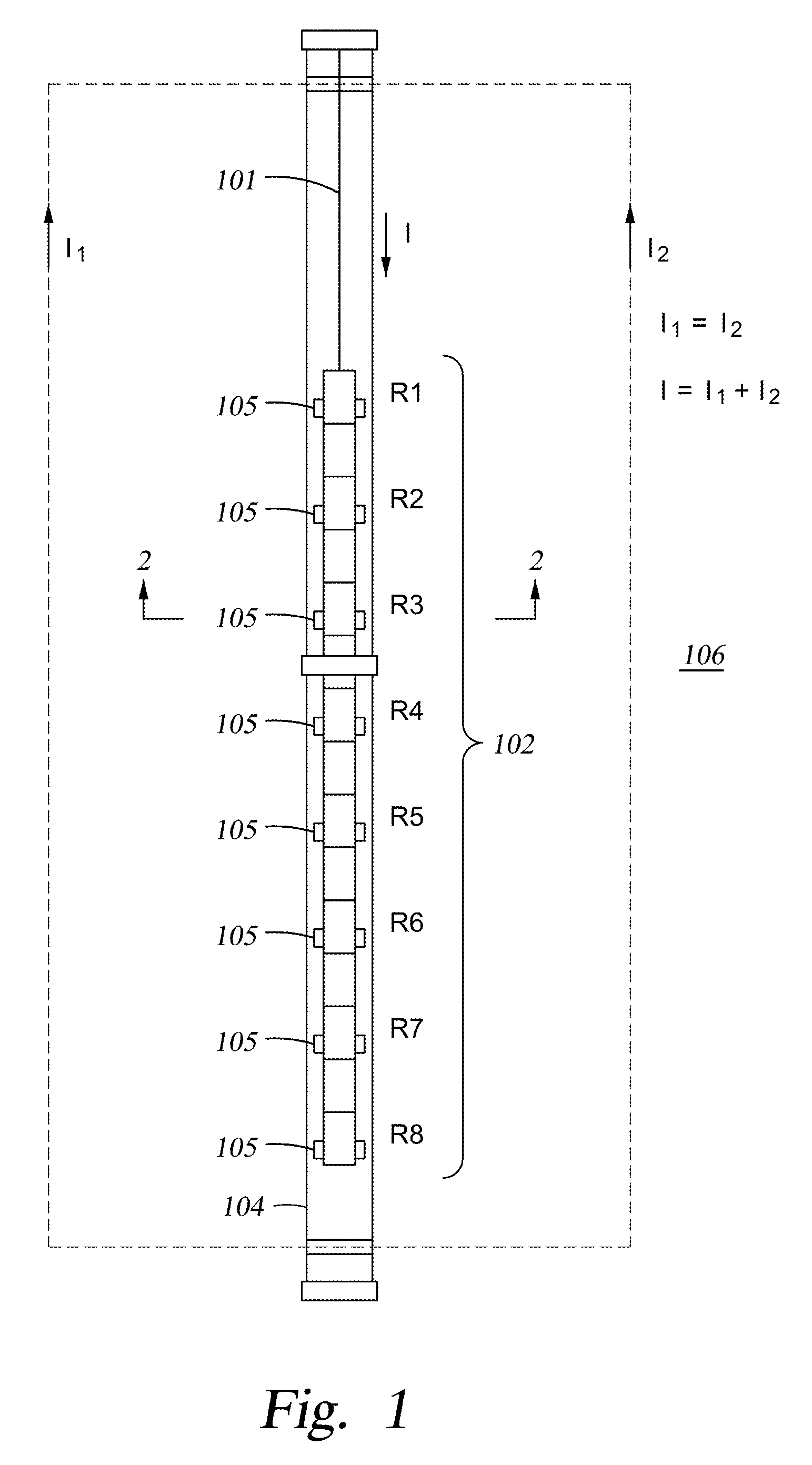
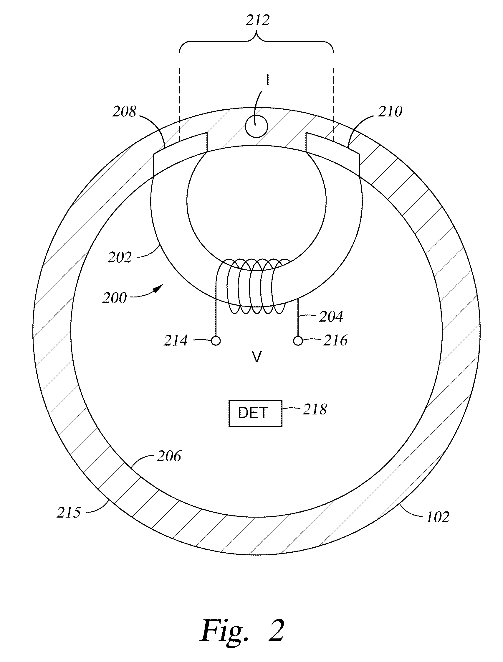
[0017]In accordance with some embodiments, a correction mechanism is provided to perform corrections of receiver measurements in a cased wellbore that are affected by induced current flowing in the casing in a longitudinal (axial) direction of the casing. A “casing” refers to any structure that lines a wellbore. In many implementations, the casing is formed of an electrically conductive and often magnetic material that allows current to flow through the casing. Axial currents do not directly affect a receiver designed to measure axial magnetic fields; however, if the casing is magnetic, the current will alter the magnetic properties of the casing and wi...


PUM


Abstract

A current sensor measures an electrical current flowing in well casing or other magnetic structure. The current sensor can be installed in a tool for performing electromagnetic (EM) induction surveying in a wellbore lined with an electrically conductive casing. The tool includes an EM element to transmit or receive a magnetic field through the casing. The measured current using the current sensor can be used to relate the change of casing effect on the EM element (e.g., an induction receiver) placed inside the well casing for performing the EM induction survey.

Description

CROSS-REFERENCE TO RELATED APPLICATIONS[0001]This application claims the benefit under 35 U.S.C. §119(e) of U.S. Provisional Application Ser. No. 61 / 119,275, entitled “Induction Coil Sensitivity Change Due to Axial Current Induced in Steel Casings,” filed Dec. 2, 2008, which is hereby incorporated by reference.BACKGROUND[0002]Geological formations forming a reservoir for the accumulation of hydrocarbons or other fluids in the subsurface of the earth contain a network of interconnected paths in which fluids are disposed that may ingress or egress from the reservoir. To determine the behavior of the fluids in this network, knowledge of both the porosity and permeability of the geological formations is desired. From this information, efficient development and management of hydrocarbon reservoirs may be achieved. For example, the resistivity of geological formations is a function of both porosity and permeability. Considering that hydrocarbons are electrically insulating and most connat...

Claims


Application Information

Patent Timeline
Patent Type & Authority Applications(United States)
IPC IPC(8): G01V3/18G01V5/04
CPCG01V5/00G01V3/28
Inventor ZHANG, HONGROSTHAL, RICHARD A.
Owner SCHLUMBERGER TECH CORP
Why Eureka
Try Eureka