Multi-Frequency Antenna

a multi-frequency antenna and antenna technology, applied in the direction of antennas, antenna details, basic electric elements, etc., can solve the problems of instability of signal transmission, design is unlikely to excite a plurality of resonant modes, etc., and achieves simplified antenna structure, reduced antenna size, and easy assembly

Inactive Publication Date: 2010-06-03
ADVANCED CONNECTEK INC
View PDF5 Cites 14 Cited by
  • Summary
  • Abstract
  • Description
  • Claims
  • Application Information

AI Technical Summary

Benefits of technology

[0008]Another objective of the present invention is to provide a multi-frequency antenna, which adopts a loop-antenna design, wherein the radiation conductors and the extension conductor are fabricated to have a serpentine layout, whereby the antenna structure is simplified, and the antenna size is greatly reduced, wherefore the antenna system of the present invention is easy to assemble for various electronic devices, and the cost thereof is decreased.
[0009]A further objective of the present invention is to provide a multi-frequency antenna, wherein the grounding conductor of the USB interface is used as the grounding connection interface of the antenna system to reduce the interference on signal transmission and promote the stability of signal transmission.
[0011]The present invention fabricates the radiation conductor to have a serpentine form to greatly increase the resonant path of the antenna and reduce the space occupied by the antenna. The present invention uses the grounding conductor of the USB interface as the grounding connection interface of the short-circuit member of the antenna system. The signal starts from the feeder member of the radiation conductor through the connection member to the grounding conductor of the USB interface and then to the ground plane of the antenna system. Thus, the radiation conductor and the grounding conductor of the USB interface are integrated into an antenna loop, which can excites a low-frequency resonant mode and a first high-frequency resonant mode. Further, the radiation conductor cooperates with the extension conductor to excite a second high-frequency resonant mode. Besides, the terminal of the extension conductor and the terminal of the connection member are close to each other and have a gap therebetween, which generates a capacitive coupling effect to modulate the impedance matching of the second high-frequency resonant mode. The first and second high-frequency resonant modes jointly form a broadband resonant mode, whereby the antenna system covers several operation frequency bands and has a characteristic of broadband. Therefore, the present invention can overcome the conventional problem that antenna miniaturization always accompanies insufficiency of frequency bands. The integrated loop antenna design and the simple layouts of the radiation conductor and the extension conductor simplify the antenna structure and decrease the antenna size, whereby the space occupied by the antenna is greatly reduced, and the antenna system can be easily assembled into various electronic products. Thus is reduced the fabrication cost.

Problems solved by technology

Such a design is unlikely to excite a plurality of resonant modes to implement a multi-frequency antenna.
Besides, using the input / output port 32 as the antenna / transmission device usually causes instability of signal transmission.

Method used


Image

  • Multi-Frequency Antenna
  • Multi-Frequency Antenna
  • Multi-Frequency Antenna

Examples


Embodiment Construction

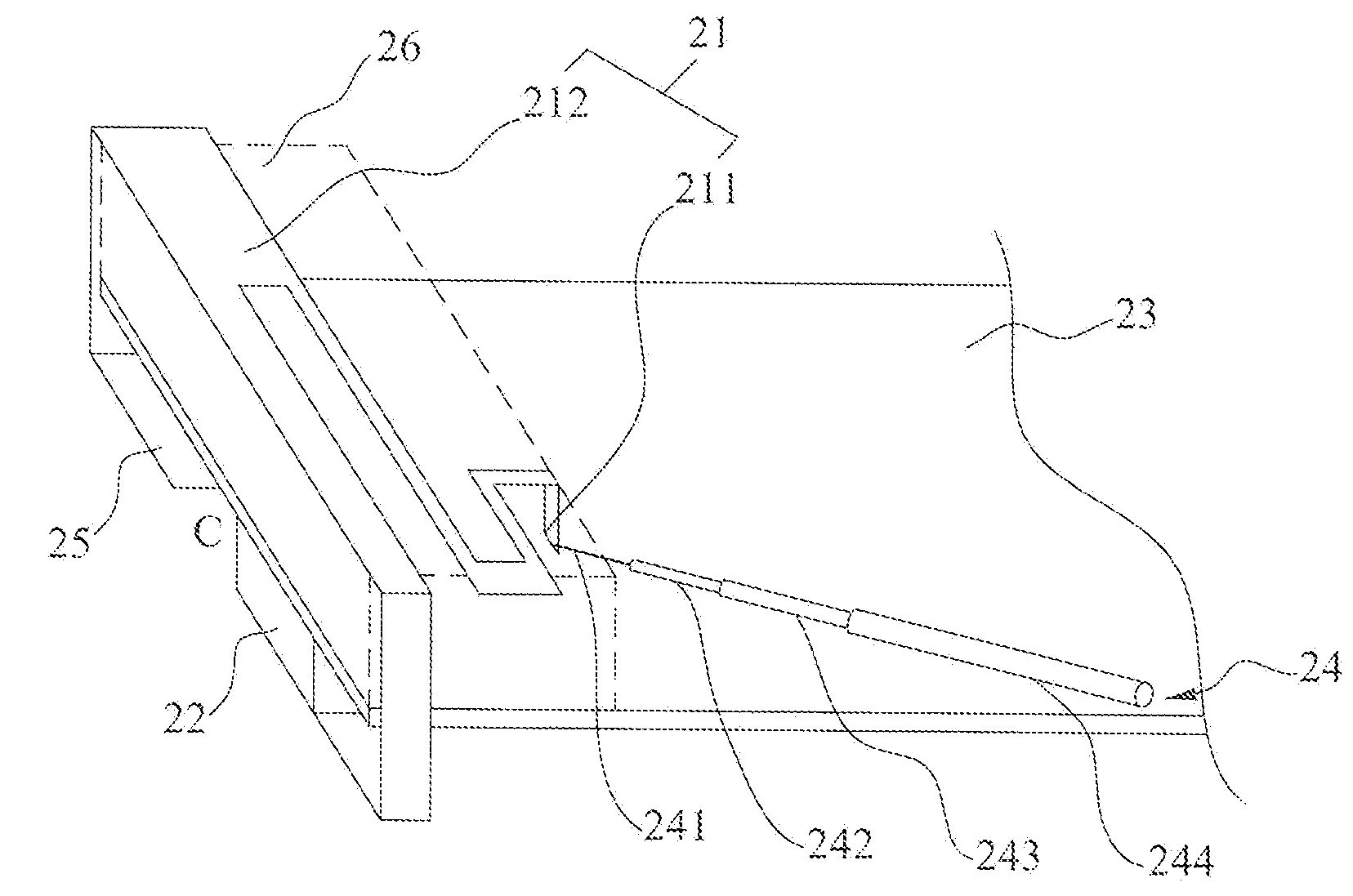
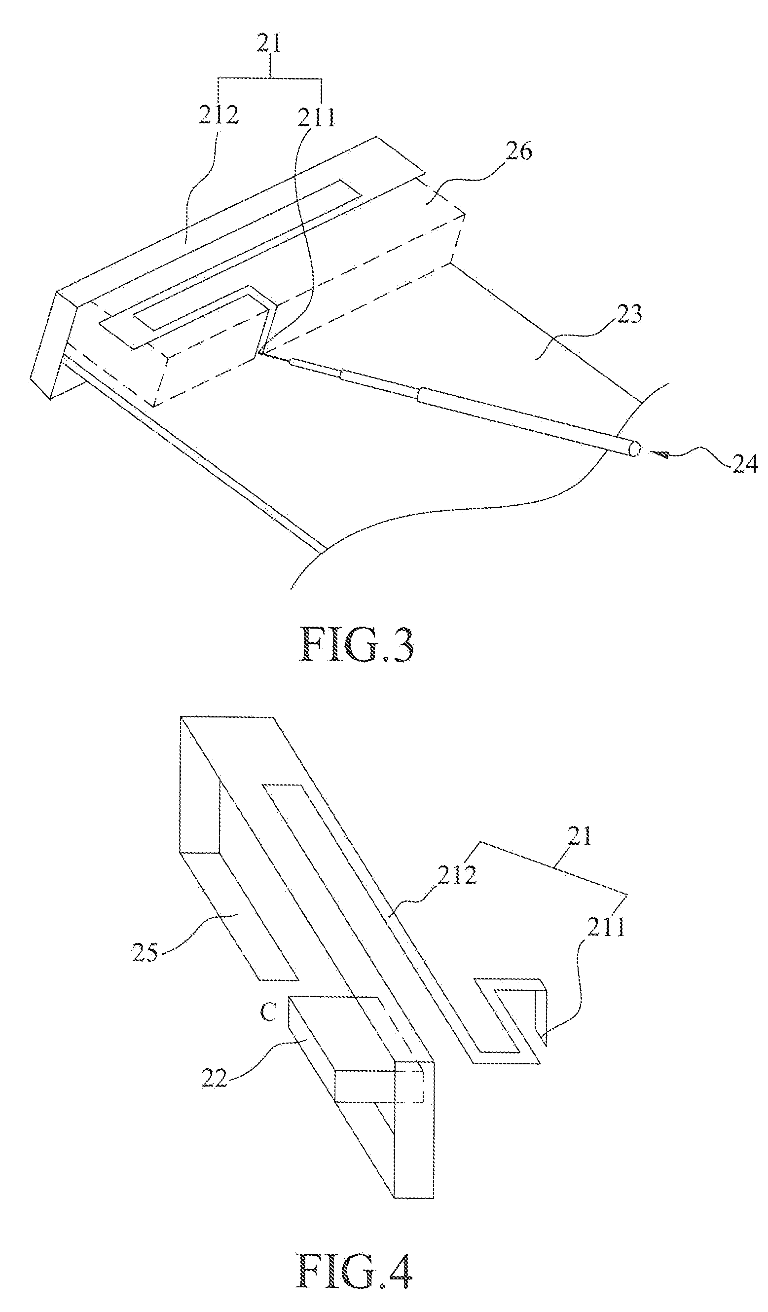
[0018]Referring to FIG. 2, a perspective view of a multi-frequency antenna according to one embodiment of the present invention is shown. The multi-frequency antenna of the present invention comprises a radiation conductor 21, a connection interface device 22, a ground plane 23, a feeder cable 24, and an extension conductor 25. The radiation conductor 21 further comprises a feeder member 211 and a connection member 212. The feeder cable 24 further comprises a central wire 241, an insulation layer 242, an external conductive layer 243 and a coating layer 244.

[0019]A microwave dielectric material 26 is used to support the radiation conductor 21 formed over the ground plane 23. The microwave dielectric material 26 is a non-metallic material and used to prevent the radiation conductor 21 from contacting the ground plane 23. The connection member 212 of the radiation conductor 21 extends serpentinely and far away from the feeder member 211 and has a terminal (not shown in the drawings). ...


PUM


Abstract

A multi-frequency antenna comprises a radiation conductor, a connection interface device, a ground plane, a feeder cable, and an extension conductor. The radiation conductor further comprises a feeder member and a connection member extending serpentinely and far away from the feeder member and having a terminal. One lateral side of the connection interface device is connected to the terminal of the connection member. Another lateral side of the connection interface device is arranged on the ground plane and electrically connected to the ground plane. The present invention adopts a loop-antenna design. In the present invention, a radiation conductor is used to excite a low-frequency resonant mode and a first high-frequency resonant mode, and an extension conductor is used to excite a second high-frequency resonant mode, whereby the antenna system covers several operation frequency bands and features broadband.

Description

BACKGROUND OF THE INVENTION[0001]1. Field of the Invention[0002]The present invention relates to a multi-frequency antenna, particularly to a multi-frequency antenna integrated with a connection interface.[0003]2. Description of the Related Art[0004]With the fast development of wireless communication, the compact, lightweight, high-sensitivity and low-cost antenna has been the mainstream. Due to the miniaturization design, omnidirectional radiation pattern, capability of mass transmitting audio / video data, and wide frequency band, the multi-frequency antenna is the most widely used antenna among all antenna products.[0005]Referring to FIG. 1, a perspective view of an “Integrated Antenna and Input / Output Port for a Wireless Communication Device” disclosed in a U.S. Pat. No. 7,231,236 is shown, wherein an input / output port 32 is arranged in the lateral of a casing 31 of a wireless communication device to function as an antenna / transmission device, whereby data is transmitted. A cover ...

Claims


Application Information

Patent Timeline
Patent Type & Authority Applications(United States)
IPC IPC(8): H01Q1/50
CPCH01Q1/38H01Q5/371H01Q9/42H01Q9/40
Inventor LIU, SHIH-CHIALEE, TIEN-CHICHIU, TSUNG-WENHSIAO, FU-REN
Owner ADVANCED CONNECTEK INC
Why Eureka
Try Eureka