Measurement method of chromatic dispersion of optical beam waveguide using interference fringe measurement system

Active Publication Date: 2010-06-03
INHA UNIV RES & BUSINESS FOUNDATION
View PDF10 Cites 20 Cited by
  • Summary
  • Abstract
  • Description
  • Claims
  • Application Information

AI Technical Summary

Problems solved by technology

This method, however, is sensitive to the time jitter and the wavelength stability of the laser, and requires a high stability even in a complicated experimental structure.
Secondly, the phase shift measuring method measures a wavelength dependent phase delays after phase-modulated optical signals are allowed to pass through a long optical fiber.
However, this method has a difficulty in measuring an accurate phase delay when the measurement wavelength is apart from a reference wavelength and the phase delay is large.
In addition, this method has another disadvantage related to a complicated measurement setup requirement.
This method also has a drawback of requiring a reference optical fiber or a waveguide of known chromatic dispersion value to obtain an absolute chromatic dispersion value of a sample.
However, since the output of the interferometer varies very sensitively to environmental instability, it is not easy to measure the wavelength of zero signal delay for both reference and sample arm beams.
This kind of sensitivity to the environmental insta

Method used


Image

  • Measurement method of chromatic dispersion of optical beam waveguide using interference fringe measurement system
  • Measurement method of chromatic dispersion of optical beam waveguide using interference fringe measurement system
  • Measurement method of chromatic dispersion of optical beam waveguide using interference fringe measurement system

Examples


Embodiment Construction

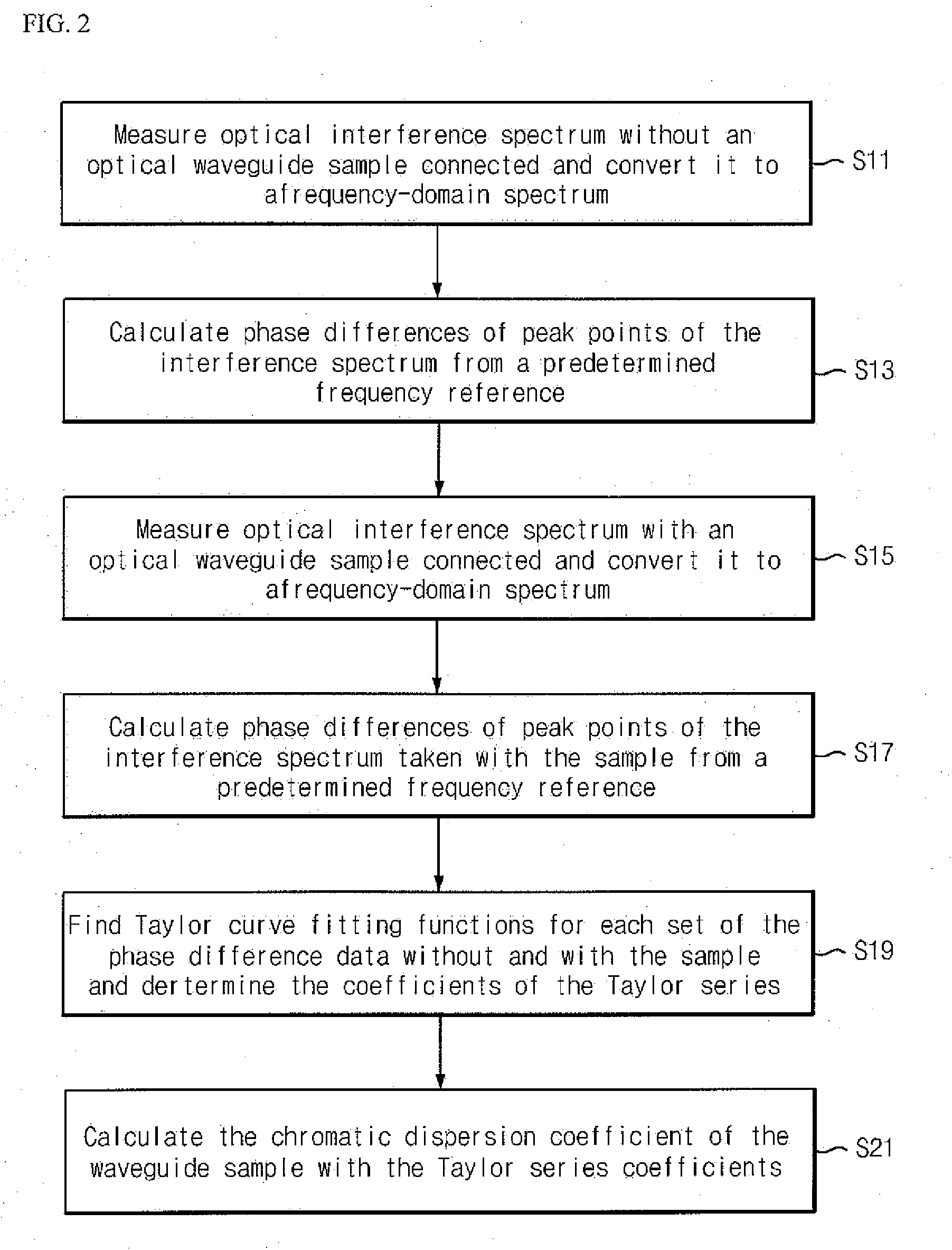
[0036]Hereinafter, a method of measuring the chromatic dispersion of an optical waveguide using an optical interferometer in accordance with an embodiment of the present invention will be described with reference to the accompanying drawings.

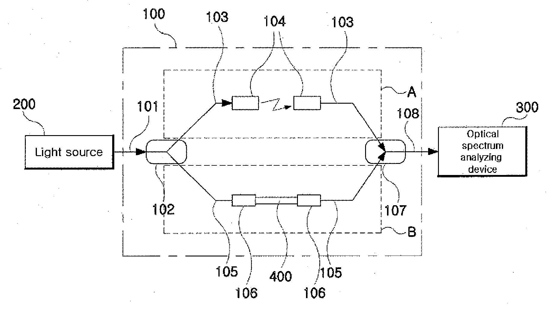
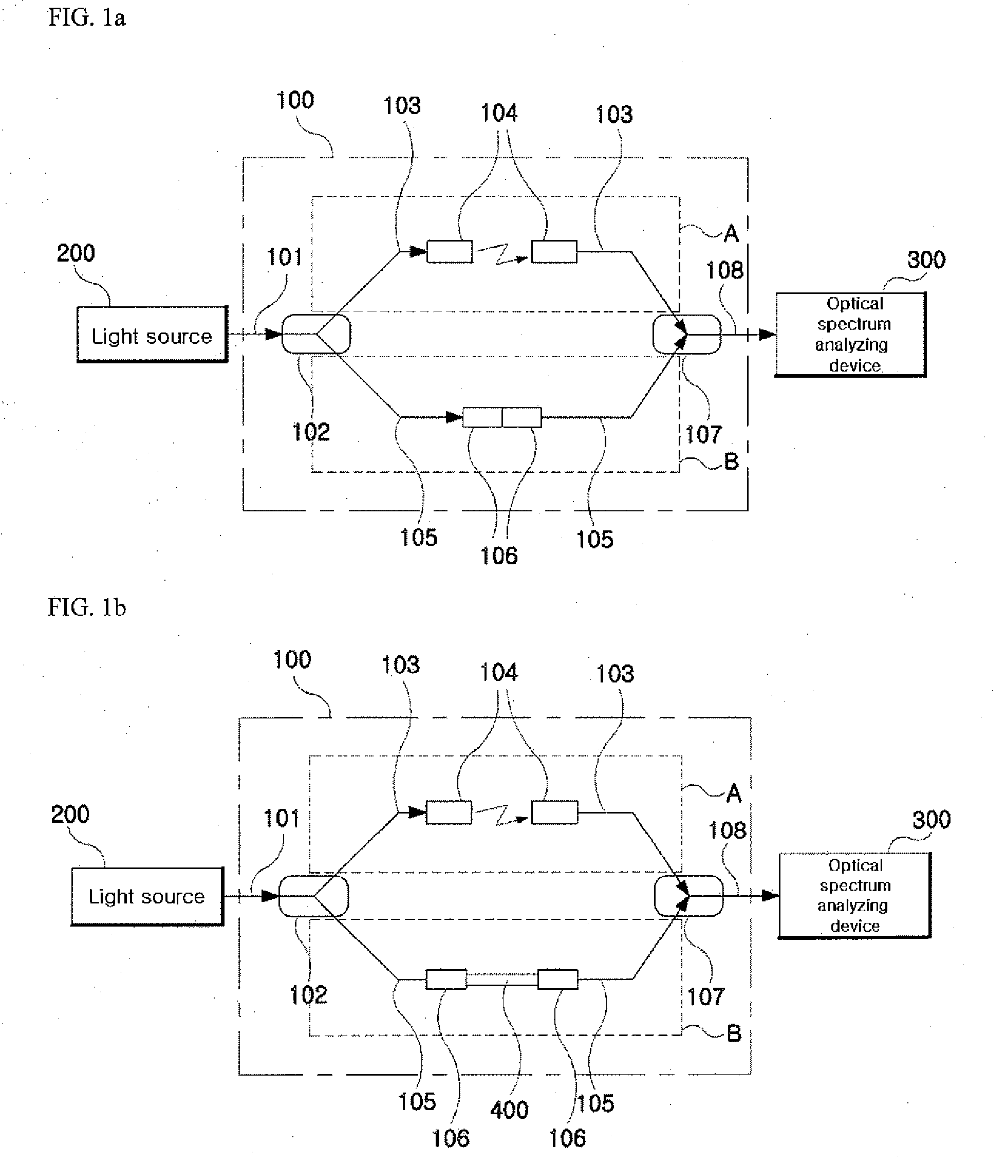
[0037]FIG. 1a and FIG. 1b show brief illustrative diagrams of an optical interference pattern measuring scheme to explain a chromatic dispersion measuring method in accordance with an embodiment of the present invention. In particular, FIG. 1a shows a brief diagram of the interference spectrum measurement scheme with no optical waveguide connected, and FIG. 1b shows a diagram of the interference spectrum measurement scheme with an optical sample waveguide connected. The optical interferometer scheme used in these figures is a Mach-Zehnder interferometer.

[0038]As shown in FIG. 1a and FIG. 1b, the interference pattern measuring system comprises a light source 200, a Mach-Zehnder interferometer 100, and an optical spectrum analyzing apparatus 300.

[...


PUM


Abstract

The present invention relates to a measurement method of the chromatic dispersion of an optical waveguide using an optical interferometer with a broadband multi-wavelength light source and an optical spectrum analyzing apparatus, wherein one arm, called “reference arm” of the interferometer's two arms has an adjustable air spacing and the other arm, called “sample arm” can contain said optical waveguide to be measured, and including the following measurement and analysis steps: measuring interference spectra of the optical beam output exiting from the said interferometer with an optical spectrum analyzing apparatus when said optical waveguide is connected to said sample arm, and when said optical waveguide is not connected to said sample arm respectively; by adjusting the reference arm length for appearance of clear interference patterns; converting the wavelength-domain interference spectra into frequency-domain interference spectra and calculating phase difference values of the interference peaks of one of the spectra from a predetermined reference peak as a function of the frequency change by counting the interference peak (or valley) points; finding a Taylor series curve fit function for each set of the phase difference value data corresponding to each of the two interference spectra; and calculating a chromatic dispersion coefficient of the optical waveguide by using the coefficients of the Taylor series curve fit functions.

Description

CROSS-REFERENCE TO RELATED APPLICATIONS[0001]This application claims the benefit of Korean Patent Application No. 10-2008-0120439, filed with the Korean Intellectual Property Office on Dec. 1, 2008, the disclosure of which is incorporated herein by reference in its entirety.BACKGROUND[0002]1. Technical Field[0003]The present invention relates to a method of measuring the chromatic dispersion of an optical beam waveguide (hereinafter referred to as “optical waveguide”) using interference fringes of an optical interferometer, more specifically to a method of measuring the chromatic dispersion coefficient of an optical waveguide using interference fringes of an optical interferometer which allows a simple and precise measurement of a chromatic dispersion property of an optical waveguide having a short length or a small chromatic dispersion value without using a complicated measuring equipment.[0004]2. Description of the Related Art[0005]The chromatic dispersion of an optical waveguide ...

Claims


Application Information

Patent Timeline
IPC IPC(8): G01N21/00G01B9/02G06F15/00
CPCG01M11/331G01M11/338G01M11/335G01J3/00G02B6/10
Inventor KIM, KYOUNGHEONKIM, SEUNGHWANLEE, SEOUNGHUNLEE, ELHANG
Owner INHA UNIV RES & BUSINESS FOUNDATION
Why Eureka
Try Eureka