
Particle counter

a technology of particle counters and counters, applied in the field of particle counters, to achieve the effect of avoiding erroneous results

Active Publication Date: 2010-06-03
SHIMADZU CORP
View PDF10 Cites 4 Cited by
  • Summary
  • Abstract
  • Description
  • Claims
  • Application Information

AI Technical Summary

Benefits of technology

[0009]The problem to be solved by the present invention is to provide a particle counter capable of accurately discriminating the signal of light scattered by real particles from the background light noise, and furthermore, capable of detecting smaller particles than before.
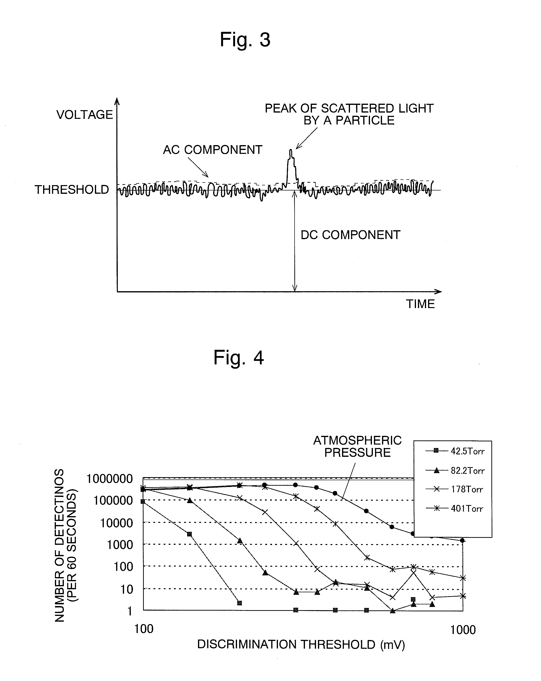
[0023]In the present invention, whether or not a particle exists is determined based on the discrimination threshold which is set in accordance with the degree of vacuum of the measurement area, or with the time average of the electrical signal of scattered light. Therefore, it is possible to avoid erroneously detecting a noise signal by molecules of gas such as nitrogen, oxygen, and other elements as a signal of scattered light of particles. Since the background light noise is smaller as the vacuum is higher (i.e. closer to the true vacuum), the discrimination threshold can be set smaller, enabling the detection of smaller particles.

Problems solved by technology

However, in conventional particle counters, the number of gas molecules existing in the measurement area is not taken into consideration, and the signal of scattered light by real particles is discriminated from the background light noise based on a specific discrimination threshold.

Method used


Image

  • Particle counter
  • Particle counter
  • Particle counter

Examples


Embodiment Construction

[0045]Hereinafter, some embodiments of the present invention are described in detail with reference to the attached drawings.

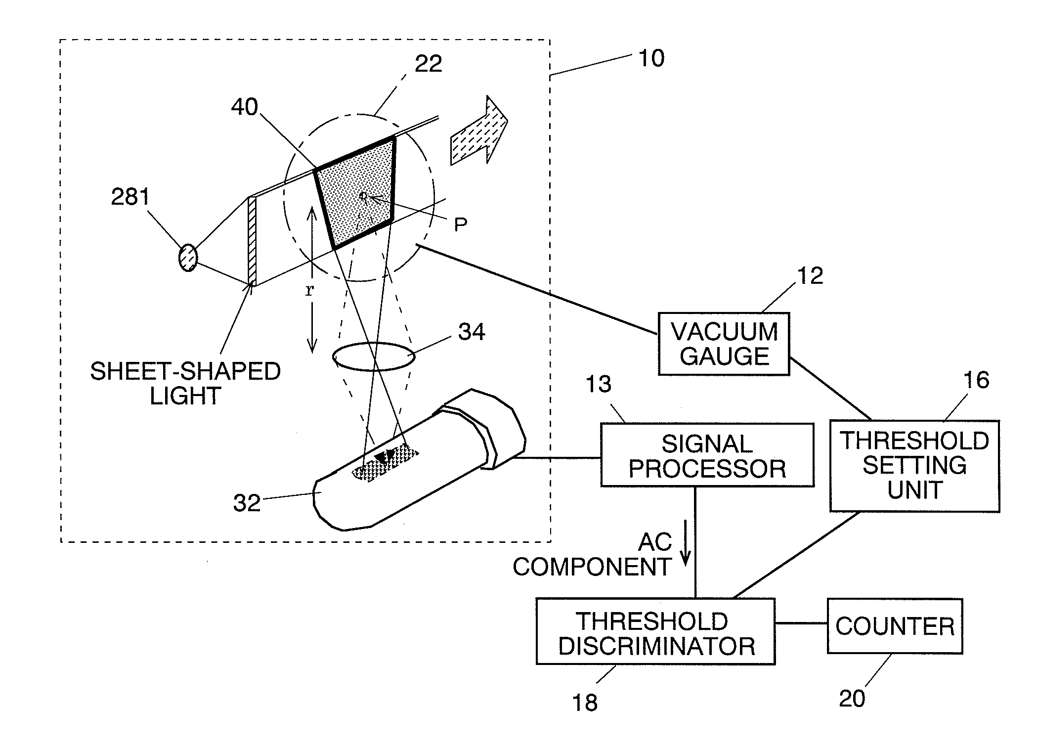
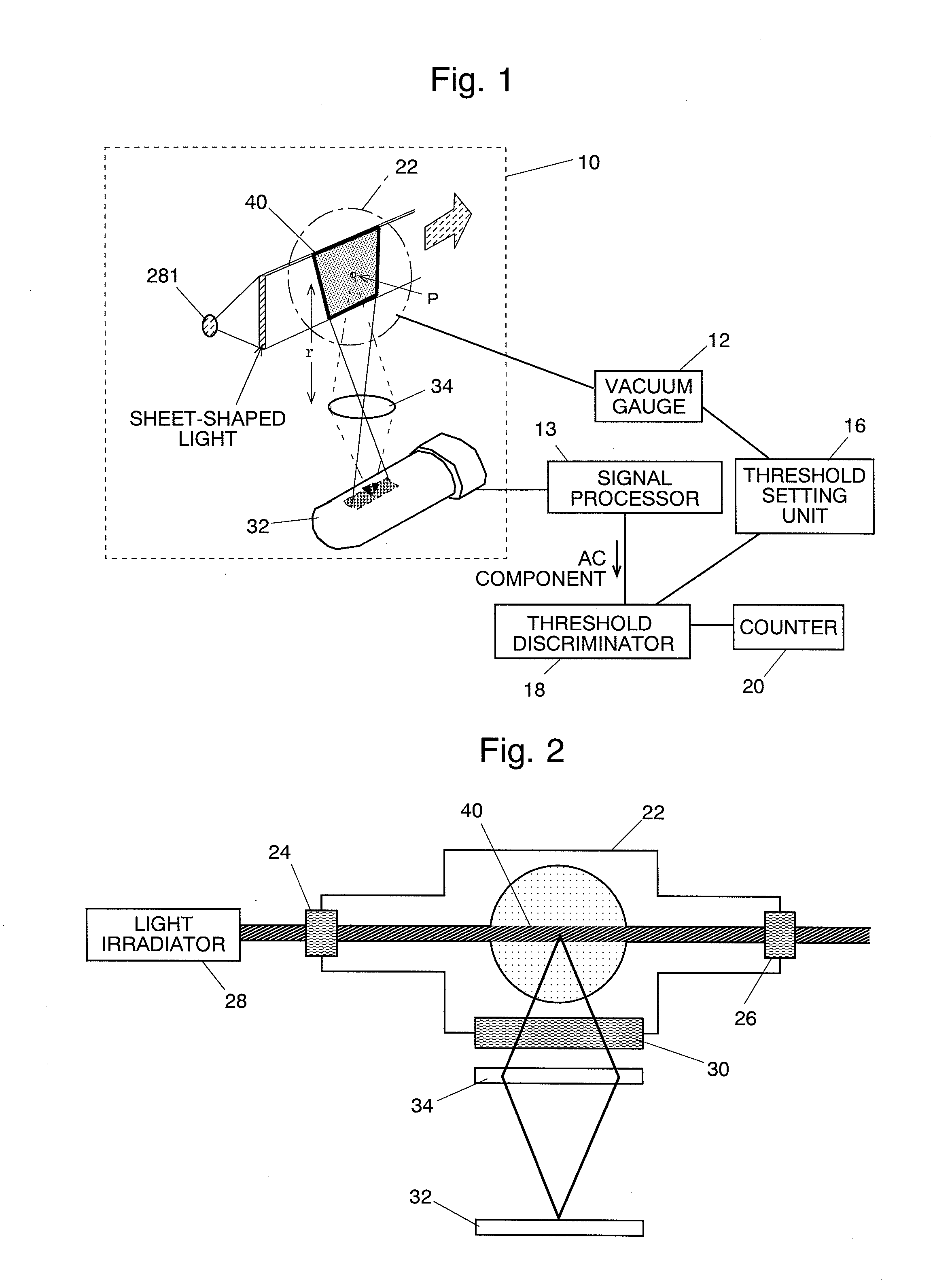
[0046]FIG. 1 is a schematic configuration diagram of the particle counter according to the first embodiment of the present invention. The particle counter 1 is composed of a detector 10, a vacuum gauge 12, a signal processor 13, a threshold setting unit 16, a threshold discriminator 18, a counter 20, and other units.

[0047]As illustrated in FIGS. 1 and 2, the detector 10 is provided on the exhaust pipe 22 of a semiconductor manufacturing equipment for example. The inside of the exhaust pipe 22 is in a vacuum state or in a near vacuum state, and a particle P flows in the direction perpendicular to the paper plane (e.g. from the front to the back of the paper plane) of FIG. 2.

[0048]The detector 10 has: a light incident window 24 and a light exit window 26 which are placed on the opposite walls of the exhaust pipe 22; a light irradiator 28 for delivering a laser l...


PUM

PropertyMeasurementUnit
timeaaaaaaaaaa
diameteraaaaaaaaaa
diameteraaaaaaaaaa

Abstract

The present invention provides a particle counter capable of accurately discriminating the signal of scattered light by real particles from the background light noise, and furthermore, capable of detecting smaller particles than conventional particle counters. The particle counter according to the present invention includes: a light irradiator for emitting light to the measurement area 40 in a vacuum state or in a near vacuum state; a scattered light detector 32 for detecting scattered light generated when the light is delivered to the measurement area 40; a discriminator 18 for determining whether or not a particle exists in the measurement area 40 by comparing the detection signal of the scattered light detector 32 and a predetermined discrimination threshold; a vacuum gauge 12 for measuring the pressure of the measurement area 40; and the threshold setting unit 16 for setting a discrimination threshold in accordance with the pressure of the measurement area 40.

Description

[0001]The present invention relates to a particle counter for counting the number of particles such as solid particles contained in the emission gas of a semiconductor manufacturing equipment and other apparatuses.BACKGROUND OF THE INVENTION[0002]Dust particles generated during the process of producing semiconductors degrade the products. Therefore, semiconductor manufacturing equipments are normally equipped with a particle counter for counting in real time the number of particles generated in the process chamber.[0003]The particle counter is generally provided in an exhaust duct from the process chamber, and includes: a light source for emitting a laser light to the measurement area in the exhaust duct; a detector for detecting the light scattered by a particle on which the laser light is irradiated; a discriminator for determining whether or not a particle exists by comparing the detection signal of the detector with a predetermined specific discrimination threshold; and other un...

Claims


Application Information

Patent Timeline
Patent Type & Authority Applications(United States)
IPC IPC(8): G01N21/00
CPCG01N15/1429G01N2015/1486G01N21/85G01N21/53
Inventor ARAKAWA, AKIRAMORI, TAKAHIROINOUE, TSUNEHIRO
Owner SHIMADZU CORP
Learn More