Imaging System Utilizing Spatial Image Oscillation

Inactive Publication Date: 2010-06-03
ZADOR ANDREW
View PDF4 Cites 26 Cited by
  • Summary
  • Abstract
  • Description
  • Claims
  • Application Information

AI Technical Summary

Benefits of technology

[0031]An analysis of the advantage of using a spatio-temporal signature to extract weak scene information in noise is also illustrative of the advantages of the present invention, over simple pixel crossing detection. A White Paper analyzing scene extrac

Problems solved by technology

The extraction of real-time velocity and noise-free detail from time-blurred frames of video has been inherently inaccurate.
The problem is that current image detection technology is based upon raster, frame-at-a-time, or arrays of independent pixels for scene capture using light (x-ray, ultraviolet, infrared or other medium) integrating pixels.
This process is limited in resolution by the number of pixels and their dimensions, and cannot avoid integrating noise into the detection process.
They have also not addressed the necessity of real-time continuous array element calibration, required for such a system to function, or the need to stabilize the image in any scene-memory plane for useful processing.
Since Gillette only calculates an estimate of the subpixel shifts, Gillette is unable to determine the portion of the magnitude of the pixel values actually attributable to the subpixel shifts.
Estimation errors in subpixel shi

Method used


Image

  • Imaging System Utilizing Spatial Image Oscillation
  • Imaging System Utilizing Spatial Image Oscillation
  • Imaging System Utilizing Spatial Image Oscillation

Examples


Embodiment Construction

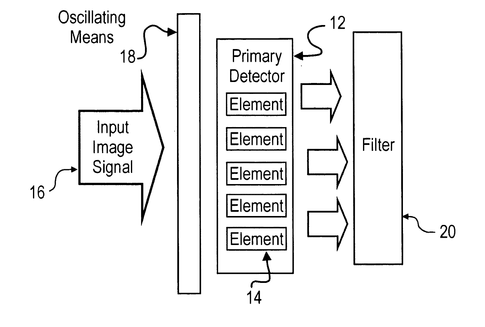
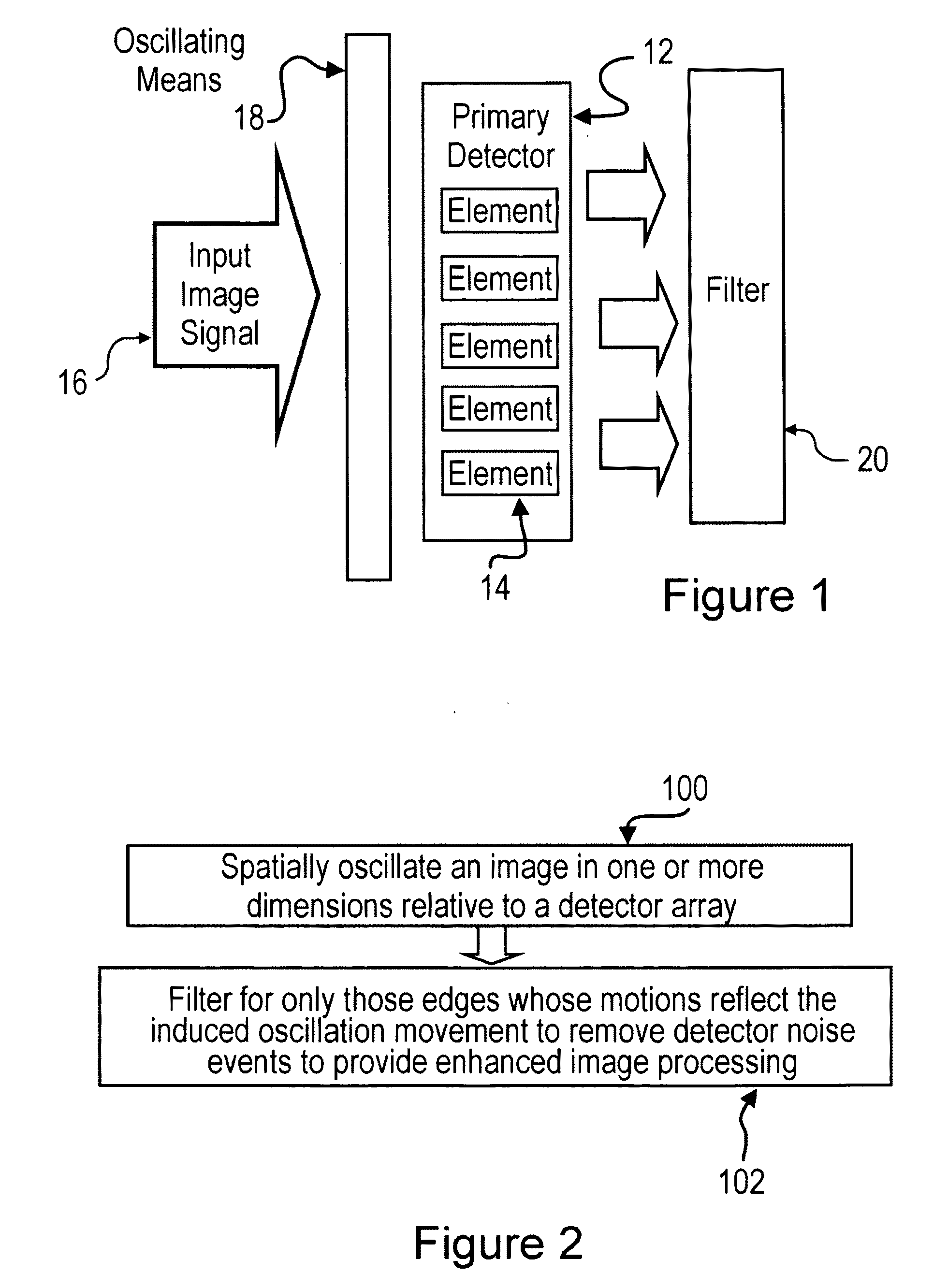
[0044]The present invention is directed to a vision system, method and apparatus utilizing spatial oscillation. As illustrated in FIG. 1, the system includes a primary detector array 12 having detector elements 14 sensitive to an input image signal 16, means 18 for inducing a spatial oscillation in the image 16 relative to the primary detector array 12, and a filter 20 for filtering the image signal according to the spatio-temporal motion signature of the induced oscillation so as to extract those elements whose motions reflect the induced oscillation, therein removing noise events to provide enhanced image quality and simplified post-processing. In a preferred embodiment, the AER retinomorphic architecture is that of Azadmehr (see citation above). For specific applications (e.g. infrared) the primary array may be bump bonded (see Delbrück citation above) to Azadmehr's AER chip using suitable materials (e.g. indium antimonide).

[0045]In a preferred embodiment of the present invention...


PUM


Abstract

An imaging system includes an image detector for producing a continuous image signal from an image received thereat; oscillation means coupled to the image detector for inducing a spatial oscillation in the image relative to the image detector; and a spatio-temporally matching filter in communication with the image detector and the oscillation means. The matching filter is configured to filter out aspects of the image signal not associated with the induced oscillation, to thereby provide enhanced image processing of the image.

Description

RELATED APPLICATIONS[0001]This patent application is a continuation-in-part of U.S. Patent Application US 20040135898, entitled “Imaging System Utilizing Spatial Image Oscillation”, filed Dec. 5, 2003, and claims the benefit of the filing date of Canadian Patent Application 2,349,828, entitled “Method, Apparatus, and System for Extracting Denoised, High-Resolution Images, Texture, and Velocity from a Lower-Resolution, Noisy Detector”, filed Jun. 6, 2001. International patent application PCTICA02100886 was published, in the English language, in publication document WO 021099745 A2, on Dec. 12, 2002.FIELD OF THE INVENTION[0002]The present invention relates generally to imaging systems and methods, and more particularly to an electronic vision system that obtains high-resolution calibrated, de-noised images and velocities from a lower-resolution detector.BACKGROUND OF THE INVENTION[0003]The extraction of real-time velocity and noise-free detail from time-blurred frames of video has bee...

Claims


Application Information

Patent Timeline
IPC IPC(8): G06K9/40
CPCG06T1/0007H04N5/357H04N5/349H04N25/48H04N25/60
Inventor ZADOR, ANDREW
Owner ZADOR ANDREW
Why Eureka
Try Eureka