Self aligning bearing and seal assembly

a self-aligning, bearing technology, applied in the direction of shaft and bearings, rotary bearings, rolling contact bearings, etc., can solve the problem of bearings seizing to the shaft, and achieve the effect of improving both bearing and seal life and lessening the friction between the inner

a self-aligning, bearing technology, applied in the direction of shaft and bearings, rotary bearings, rolling contact bearings, etc., can solve the problem of bearings seizing to the shaft, and achieve the effect of improving both bearing and seal life and lessening the friction between the inner

US20100135606A1Active Publication Date: 2010-06-03RELADYNE RELIABILITY SERVICES INC

Image

  • Self aligning bearing and seal assembly
  • Self aligning bearing and seal assembly
  • Self aligning bearing and seal assembly

Examples


Embodiment Construction

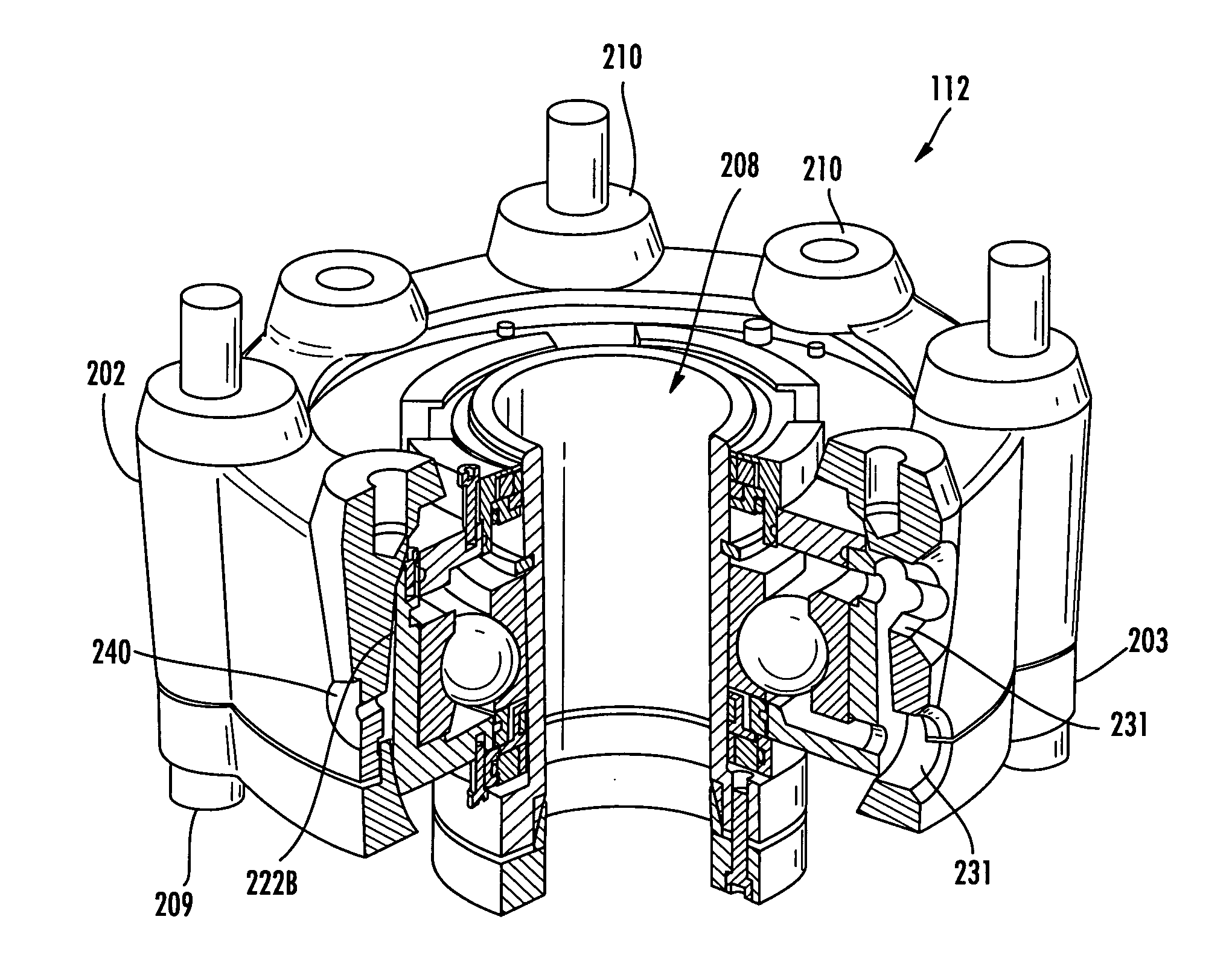
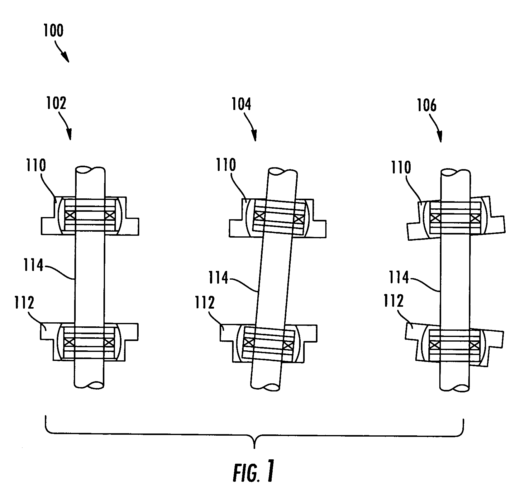
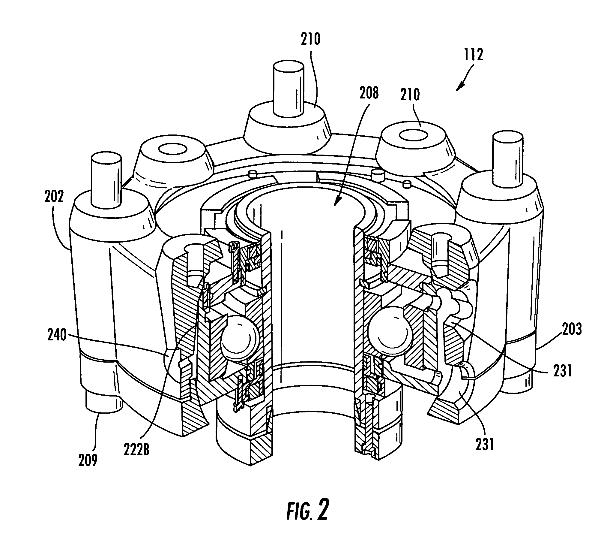
[0029]The present invention will now be described more fully hereinafter with reference to the accompanying drawings in which exemplary embodiments of the invention are shown. However, this invention may be embodied in many different forms and should not be construed as limited to the embodiments set forth herein. These exemplary embodiments are provided so that this disclosure will be both thorough and complete, and will fully convey the scope of the invention to those skilled in the art. Like reference numbers refer to like elements throughout the various drawings. To achieve the foregoing and other objects, and in accordance with the purposes of the invention as embodied and broadly described herein, the present invention provides various embodiments of a self aligning bearing and seal assembly.

[0030]In various exemplary embodiments, the present invention provides self aligning bearing and seal assemblies operable for use with any rotating machinery, including but not limited to:...


PUM


Abstract

A self aligning bearing and seal assembly including a bearing housing operable to mount to a surface, a bearing unit seated within the bearing housing and having an outer race, an inner race, and at least one ball intermediate the outer and inner race. The self aligning bearing and seal assembly also includes a pivot assembly having a shaft sleeve operable for receiving and maintaining a rotatable shaft and being disposed in the bearing housing and in operational contact with the inner race of the bearing unit. The pivot assembly allows for a degree of angular misalignment between the surface and the shaft greater than three degrees.

Description

CROSS-REFERENCE TO RELATED APPLICATION(S)[0001]The present non-provisional patent application claims priority to U.S. Provisional Patent Application Ser. No. 61 / 046,549, filed Apr. 21, 2008, and entitled “SELF ALIGNING BEARING AND SEAL ASSEMBLY,” which is incorporated in full by reference herein.FIELD OF THE INVENTION[0002]The present invention relates generally to bearing and seal assemblies, and more particularly, to self aligning bearing and seal assemblies operable for use with air cooled heat exchangers, chemical mixers and agitators, machine applications and the like where lubricated bearing assemblies are employed.BACKGROUND OF THE INVENTION[0003]Conventionally, self aligning bearings such as spherical roller bearings or spherical Outer Diameter (OD) bearings have been used to correct and / or address angular or radial misalignment between two bearings disposed upon a common shaft or a bearing disposed upon a fixed machine element. Conventionally, a seal is provided about a rot...

Claims


Application Information

Patent Timeline
03 Jun 2010
Publication
US20100135606A1
IPC
F16C33/76
CPC
F16C23/08; F16C33/76; F16C33/6685; F16C33/6659; F16C19/06; F16C35/042; F16C35/077
Inventors
EHLERT, CHARLES WAYNE; DUNCAN, PATRICK WILSON