Contact terminal for electronic device

a contact terminal and electronic device technology, applied in the direction of coupling device connection, coupling device details, fixed connection, etc., can solve the problems of reducing the productivity of manufacturing a product, increasing production costs, and difficult assembly of fabricated components to a product, so as to reduce labor and cost, simple and less costly manufacturing

Inactive Publication Date: 2010-06-03
SAMSUNG ELECTRONICS CO LTD
View PDF4 Cites 12 Cited by
  • Summary
  • Abstract
  • Description
  • Claims
  • Application Information

AI Technical Summary

Benefits of technology

[0019]Accordingly, the present invention provides a contact terminal, which can reduce the labor and cost required for fabricating electronic devices with a simply and less costly manufacture and assembly processes.

Problems solved by technology

However, such a conventional contact terminal has a disadvantage in that its fabricated components are difficult to be assembled to a product.
This reduces the productivity of manufacturing a product while increasing production costs.
Also, since a conventional contact terminal has no structure for preventing a contact member from being deformed when detaching from a fixing member, there is a problem in that the defect rate of products increases due to excessive protrusion of a connecting projection to the outside of the electronic device.
Furthermore, the conventional contact terminal requires intermediate components, such as the contact terminal, the connecting member, and the socket, from the battery pack to the circuit board, and thus due to the interconnection loss between respective components, the consumption of electrical power of the battery pack is increased.

Method used


Image

  • Contact terminal for electronic device
  • Contact terminal for electronic device
  • Contact terminal for electronic device

Examples


Embodiment Construction

[0040]Exemplary embodiments of the present invention will be described in detail with reference to the accompanying drawings. For the purposes of clarity and simplicity, a detailed description of known functions and configurations incorporated herein is omitted to avoid making the subject matter of the present invention unclear.

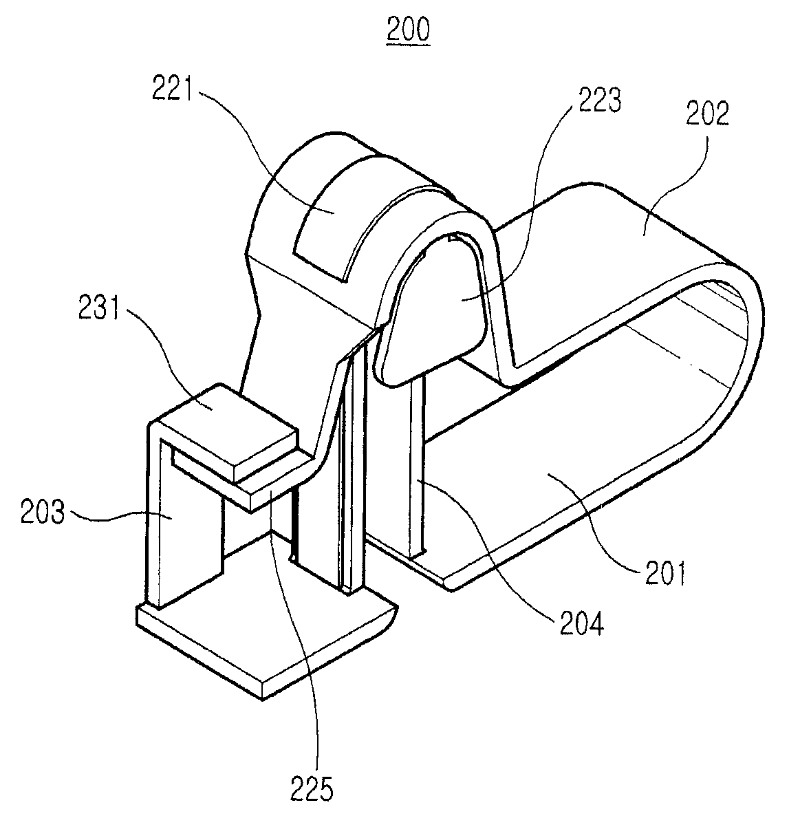
[0041]Referring to FIGS. 4 and 5, a contact terminal 200 of an electronic device, according to an embodiment of the present invention, includes a fixing member 201, a contact member 202, and a limiting member 203, and may include a supporting member 204 for securing durability.

[0042]The contact terminal 200 is for the connection of a battery pack in the description of an embodiment of the present invention, but can be applied to other devices for connection between electronic devices, or between an electronic device and an additional device (such as a terminal for the connection of a SIM card, an interface connector for a cellular phone, a USB connector of a ...


PUM


Abstract

A contact terminal of an electronic device includes: a fixing member; a contact member extending from the fixing member and a limiting member and extending from the fixing member where one end portion of the limiting member restrains one end portion of the contact member, wherein the contact terminal provides an elastic force upon the contact member in a direction away from the fixing member, and a range where the contact member moves away from the fixing member is limited since the end portion of the limiting member restrains the end portion of the contact member. The disclosed contact terminal can be directly mounted on a circuit board by using a surface mounting device (SMD) process, thereby reducing production costs and interconnection loss.

Description

CLAIM OF PRIORITY[0001]This application claims the benefit of the earlier filing date, pursuant to 35 USC 119, to that patent application entitled “Contact Terminal For Electronic Device” filed with the Korean Intellectual Property Office on Nov. 28, 2008 and assigned Serial No. 10-2008-0119998, the contents of which are incorporated herein by reference.BACKGROUND OF THE INVENTION[0002]1. Field of the Invention[0003]The present invention relates to an electronic device, such as a cellular phone, a car navigation, and a computer, and more particularly to a contact terminal to be used for the connection of an additional device to an electronic device.[0004]2. Description of the Related Art[0005]An electronic device, such as a cellular phone, a car navigation, and a computer, is provided with various types of connectors for the connection of an additional device. For example, the connectors may be represent a USB (universal serial bus) connector that connects to a USB-capable memory de...

Claims


Application Information

Patent Timeline
Patent Type & Authority Applications(United States)
IPC IPC(8): H01R4/48
CPCH01R12/57H01R13/2442H01R13/2407H01R2201/16H01R12/55
Inventor KIM, HO-SUBAEK, JEONG-MI
Owner SAMSUNG ELECTRONICS CO LTD
Why Eureka
Try Eureka