
Controlling a slave drive with dynamic determination of the dynamics of the master axis

Active Publication Date: 2010-06-03
SIEMENS AG
View PDF1 Cites 16 Cited by
  • Summary
  • Abstract
  • Description
  • Claims
  • Application Information

AI Technical Summary

Benefits of technology

[0010]In one embodiment of the present invention, if the dynamics with which the drive is controlled exceeds the upper dynamics limit, the control device decides for each of the master axes independently of the other master axes whether and, if appropriate, to what extent it modifies the determination of the current desired values for this master axis. This refinement simplifies the mode of procedure. A more simple programming results particularly in the case of a software implementation of the operating method.
[0014]In another embodiment of the present invention, the control device is provided with types in addition to the profiles. In this case, the control device can into consideration for each master axis the respective type when deciding whether and, if appropriate, to what extent to modify the determination of the current desired values for this master axis. The type assignment can, for example, serve to distinguish rapid movements, coarse processing, fine processing and final processing. Other distinctions are also possible. Thus, for example, the modification of the determination of the current desired values for a movement corresponding to a roughing operation (coarse processing) can be more readily tolerated than the modification, for example, for a movement that corresponds to a finishing operation (fine processing) or a grinding operation (final processing).
[0020]According to another aspect of the invention, an operating program including has machine code can be executed directly by a control device. The execution of the machine code by the control device has the effect that the control device carries out an operating method according to the invention.

Problems solved by technology

It is disadvantageous in this mode of procedure that the possible dynamics of the respective drive is possibly not optimally utilized, thus resulting in suboptimal processing times.
This case also results in suboptimal processing times. Moreover, a—mostly considerable—additional outlay for programming is required.
This mode of procedure is, for one thing, extremely expensive and complex.
Moreover, it is scarcely possible to take account of temporally variable magnitudes.
The problems explained above can occur not only with position controlled drives.
The same problems can also occur when control of rotational speed, acceleration, torque, etc. is undertaken.

Method used


Image

  • Controlling a slave drive with dynamic determination of the dynamics of the master axis
  • Controlling a slave drive with dynamic determination of the dynamics of the master axis
  • Controlling a slave drive with dynamic determination of the dynamics of the master axis

Examples


Embodiment Construction

[0037]Throughout all the Figures, same or corresponding elements may generally be indicated by same reference numerals. These depicted embodiments are to be understood as illustrative of the invention and not as limiting in any way. It should also be understood that the figures are not necessarily to scale and that the embodiments are sometimes illustrated by graphic symbols, phantom lines, diagrammatic representations and fragmentary views. In certain instances, details which are not necessary for an understanding of the present invention or which render other details difficult to perceive may have been omitted.

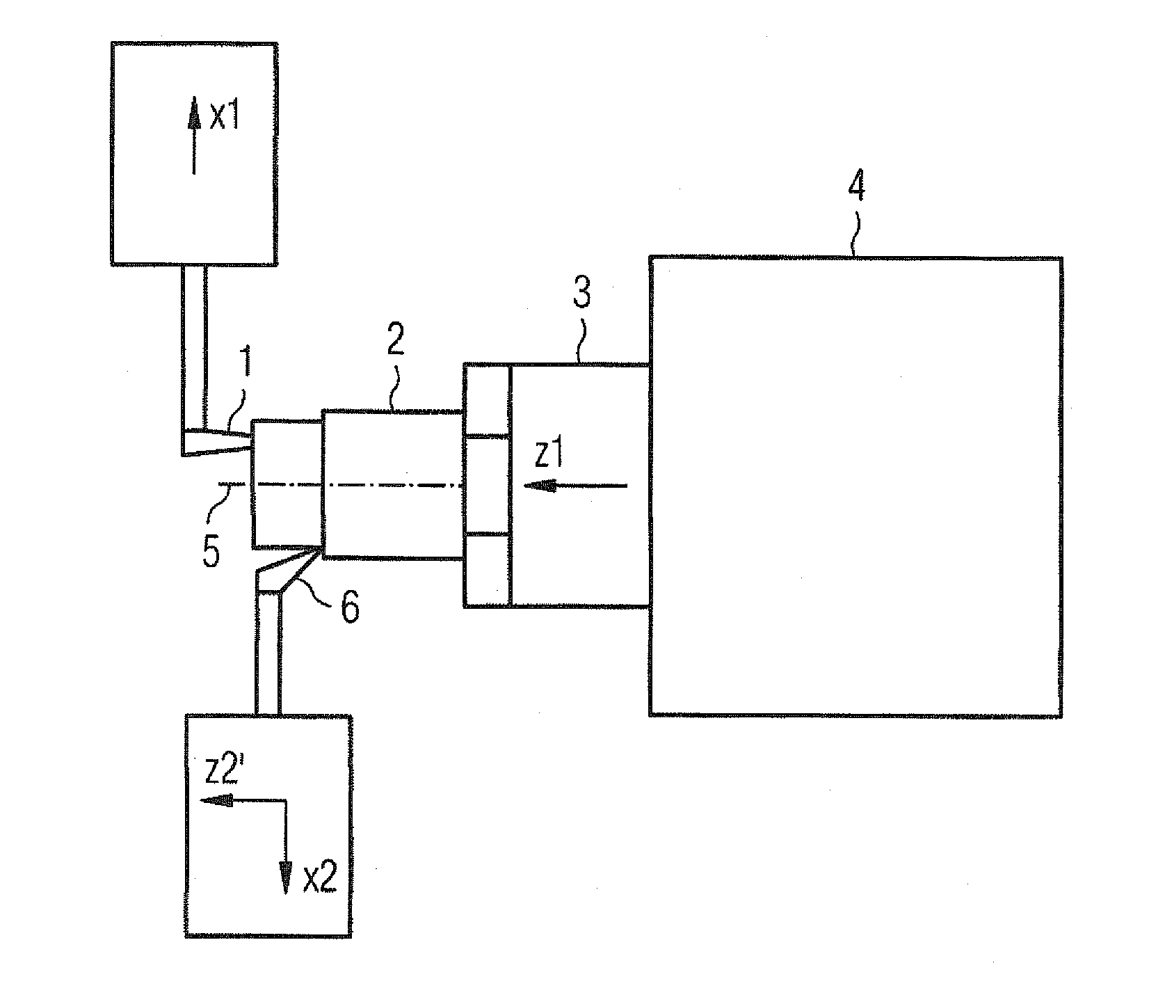
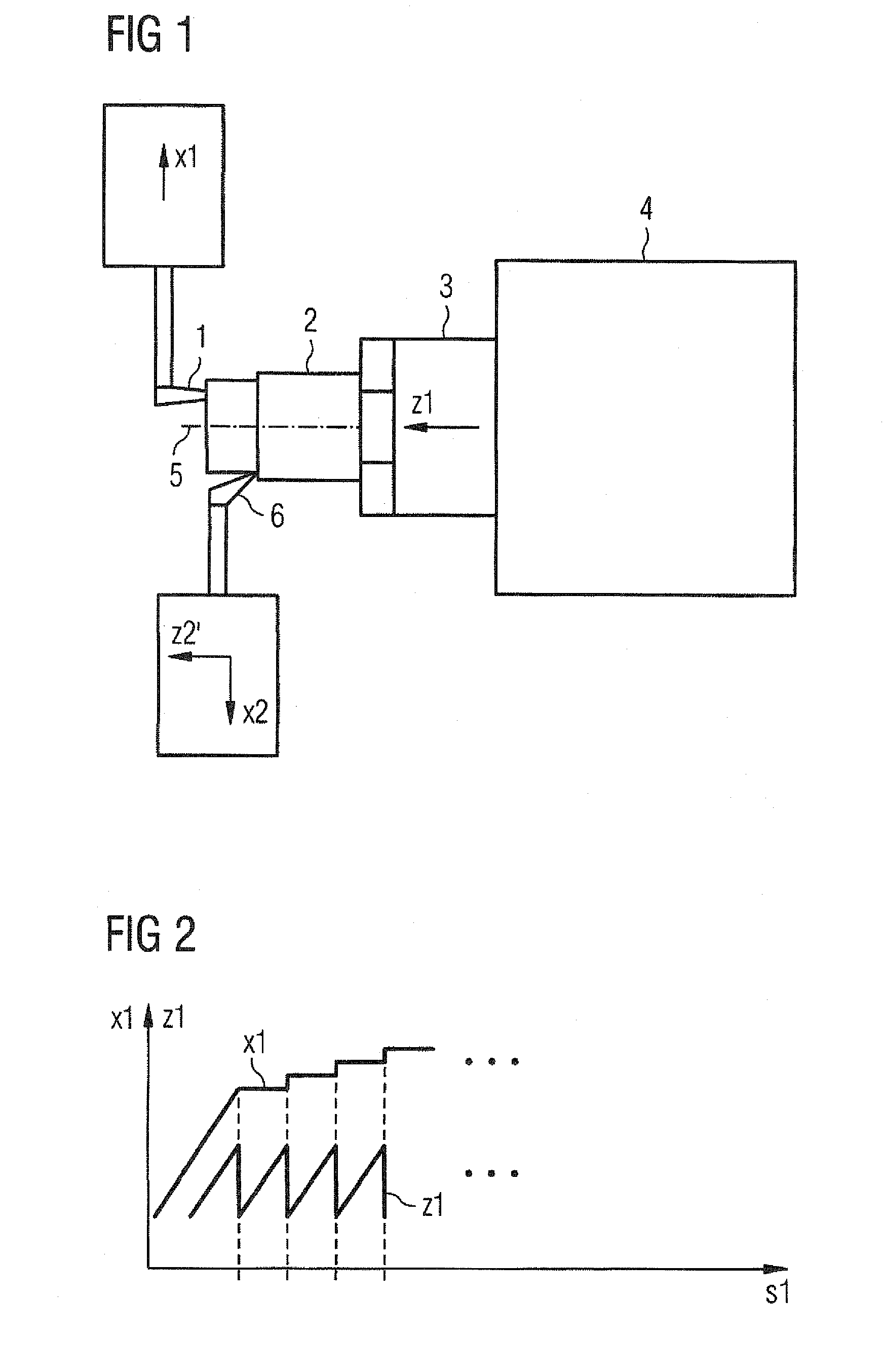
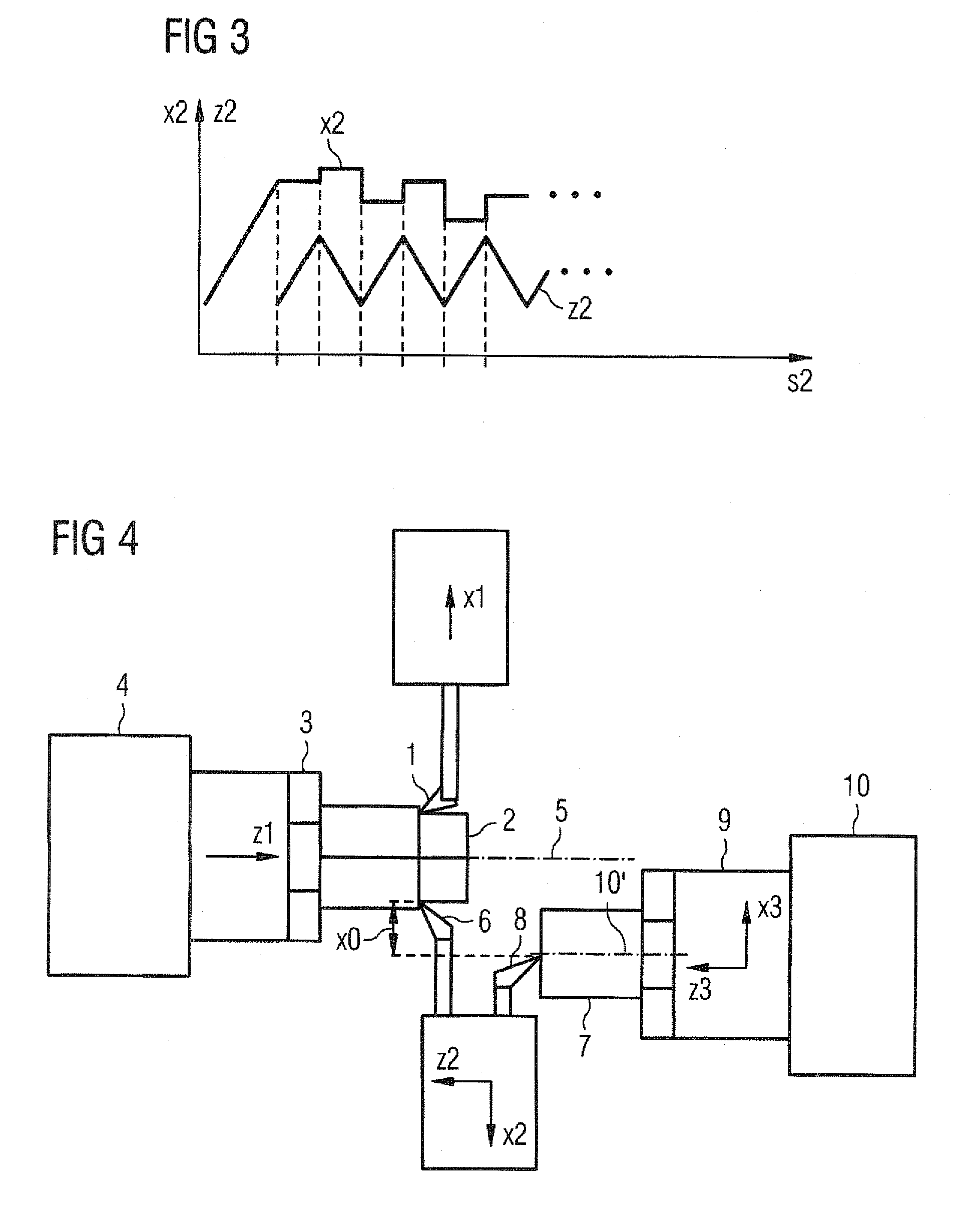
[0038]FIGS. 1 to 5 relate to machines and machining operations and are provided for a better understanding of the invention. Turning now to FIG. 1, there is shown a first tool 1 for processing a first workpiece 2. For this purpose, the first workpiece 2 is clamped in a workpiece chuck 3 of a first spindle 4 and rotated with a first spindle drive (not illustrated in more deta...


PUM


Abstract

A control device and a method for controlling several master axes in a machine, for example a production machine, is disclosed. The disclosed method includes the steps of defining profiles of desired values for a plurality of master axes, determining for each master axis a current desired value and also a current desired value for a slave axis using a logic combination rule, controlling a first drive in accordance with the current desired value of the slave axis, and if the dynamics controlling the first drive exceeds an upper dynamics limit, starting at the next clock pulse to modify determination of the current desired values for at least one of the master axes, and controlling the first drive with a reduced dynamics until the reduced dynamics falls below a lower dynamics limit.

Description

CROSS-REFERENCES TO RELATED APPLICATIONS[0001]This application claims the priority of European Patent Application, Serial No. EP08020567, filed Nov. 26, 2008, pursuant to 35 U.S.C. 119(a)-(d), the content of which is incorporated herein by reference in its entirety as if fully set forth herein.BACKGROUND OF THE INVENTION[0002]The present invention relates to a control device, for example for controlling multi-axes movement of a production machine, a method for operating such control device, and an operating program which can be executed on a control device of this type. The present invention also relates to a data medium on which an operating program is stored in machine-readable form.[0003]Workpieces are sometimes fabricated by performing several processing steps simultaneously. Various procedures are known for preventing application of excess stress on the axes. For example, the possible dynamics of the drives that carry out superposed movements can be divided statically, for exam...

Claims


Application Information

Patent Timeline
IPC IPC(8): G05B13/02
CPCG05B2219/50233G05B19/4163
Inventor BAUER, PETERHERTINGER, KLAUSSTIEHLER, HORSTTOLKMITT, TOMWEBER, CURDDE LEVIE, HEINO
Owner SIEMENS AG
Learn More