OTEC System

a technology of otec and clathrate, applied in the direction of electric generator control, machines/engines, mechanical equipment, etc., can solve the problems of reducing the amount of energy required to run an otec plant, and reducing the overall benefit of otec power generation, so as to achieve the effect of less or no energy, positive buoyancy of clathrate compound

Active Publication Date: 2010-06-10
LOCKHEED MARTIN CORP
View PDF17 Cites 16 Cited by
  • Summary
  • Abstract
  • Description
  • Claims
  • Application Information

AI Technical Summary

Benefits of technology

[0006]The present invention provides an OTEC system that comprises a self-contained, submersible, OTEC plant. The OTEC plant includes an electrical generation system and a chamber for containing a bulk thermal mass. The OTEC plant is movable between a first depth of a body of water, having a first temperature, and a second depth of the body of water, having a second temperature that is different than the first temperature. White the OTEC plant is at the first depth, the thermal mass attains a temperature based on the water at the first depth. When the OTEC plant moves from the first depth to the second depth, the OTEC plant insulates and transports the thermal mass, in bulk, along with it. As a result, when the OTEC plant is positioned at the second depth, the thermal mass can provide a local heat sink / source that can be thermally coupled to the electrical generation system. Thus, the need to pump water from one depth to the other, through a long water conduit, is obviated. Further, in some embodiments, the OTEC plant is reconfigurable so that can generate electrical energy while positioned at either depth.

Problems solved by technology

Although a promising technology, to date, the use of OTEC power generation has been limited by a number of technical challenges.
First, the significant amount of energy required to run an OTEC plant reduces its overall benefits.
Second, conventional OTEC plants are highly susceptible to damaging winds, waves, and hurricanes and other storms.
Finally, an OTEC plant requires complex and expensive infrastructure to enable its deployment.

Method used


Image

  • OTEC System
  • OTEC System
  • OTEC System

Examples


Embodiment Construction

[0023]The following terms are defined for use in this Specification, including the appended claims:

[0024]Physically-connected means in direct, physical contact and affixed (e.g., a mirror that is mounted on a linear-motor).

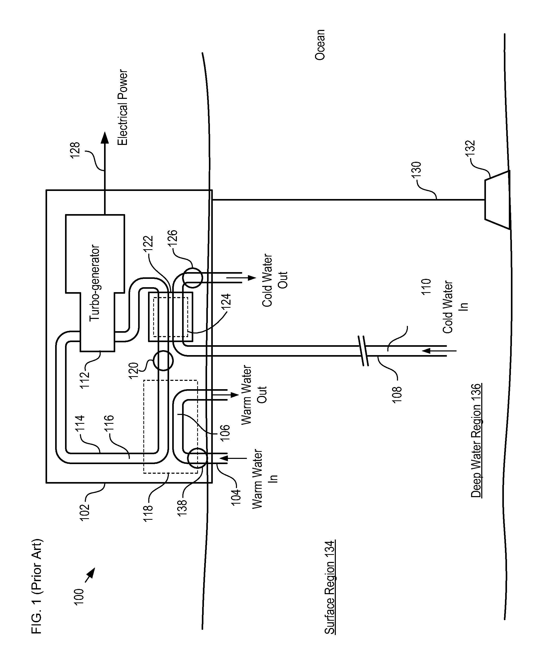
[0025]FIG. 1 depicts a schematic diagram of a portion of a typical OTEC power generation system in accordance with the prior art. OTEC system 100 comprises platform 102, surface water conduit 104, deep water conduit 108, turbogenerator 112, closed-loop conduit 114, heat exchanger 118, pump 120, and condenser 122.

[0026]Platform 102 is a conventional floating energy-plant platform. Platform 102 is anchored to the ocean floor by mooring line 130, which is connected to anchor 132. Anchor 132 is embedded in the ocean floor. In some instances, platform 102 is unanchored to the ocean floor and platform 102 is allowed to drift, such as in what is commonly referred to as a “grazing plant.”

[0027]Surface water conduit 104 is a large-diameter pipe suitable for drawing water f...


PUM


Abstract

An Ocean Thermal Energy Conversion (OTEC) system comprising a self-contained submersible OTEC plant is disclosed. The OTEC plant comprises a electrical generation system and a thermal mass whose temperature is based on the temperature of water at a first depth of a body of water. The OTEC plant is moved to a second depth of the body of water, wherein water at the second depth is a different temperature that the water at the first depth. The OTEC system generates electrical energy based on a difference in the temperatures of the water at the second depth and the temperature of the thermal mass. The OTEC system is able to generate electrical energy at either of the first depth and the second depth.

Description

FIELD OF THE INVENTION[0001]The present invention relates to power generation in general, and, more particularly, to ocean thermal energy conversion.BACKGROUND OF THE INVENTION[0002]Non-petroleum-based energy generation is an area of high technical and political interest. Systems that produce energy without the combustion of petroleum products potentially offer alternatives to conventional energy generation plants that are renewable, cleaner, potentially cheaper, and potentially more reliable.[0003]Ocean thermal energy conversion (OTEC) is one such promising energy technology. An OTEC system converts solar radiation to electrical energy by using a naturally occurring temperature difference between water at the surface of a large body of water and water thousands of meters deep to drive a power-producing cycle. As long as the temperature between the warm surface water and the cold deep water differs by about 20° C., an OTEC system can produce a significant amount of power. Large bodi...

Claims


Application Information

Patent Timeline
Patent Type & Authority Applications(United States)
IPC IPC(8): F03G7/05
CPCY02E10/34F03G7/05Y02E10/30
Inventor HOWARD, ROBERT JAMESNAGURNY, NICHOLAS J.MEYER, LAURIE E.RAPP, JOHN W.
Owner LOCKHEED MARTIN CORP
Why Eureka
Try Eureka