Transparent heat spreader for leds

a heat spreader and led technology, applied in the field of light-emitting diodes, can solve the problems of detracting from the overall effectiveness and desirability of leds, reducing heat efficiency of leds, and producing more heat, so as to facilitate heat flow and facilitate transmission

Active Publication Date: 2010-06-10
BRIDGELUX INC
View PDF7 Cites 109 Cited by
  • Summary
  • Abstract
  • Description
  • Claims
  • Application Information

AI Technical Summary

Benefits of technology

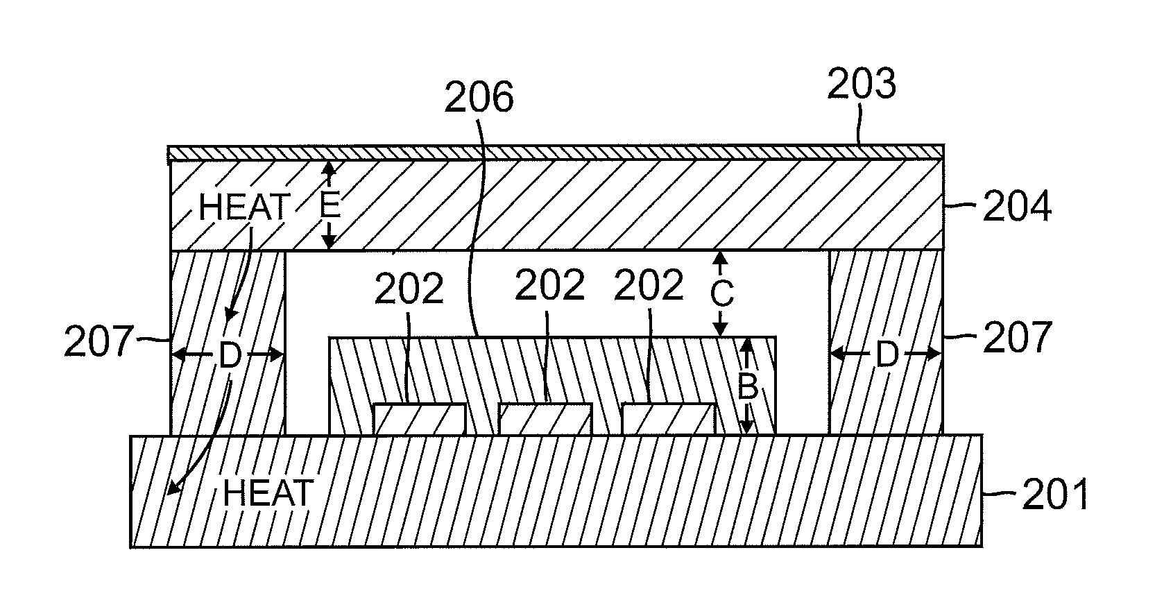
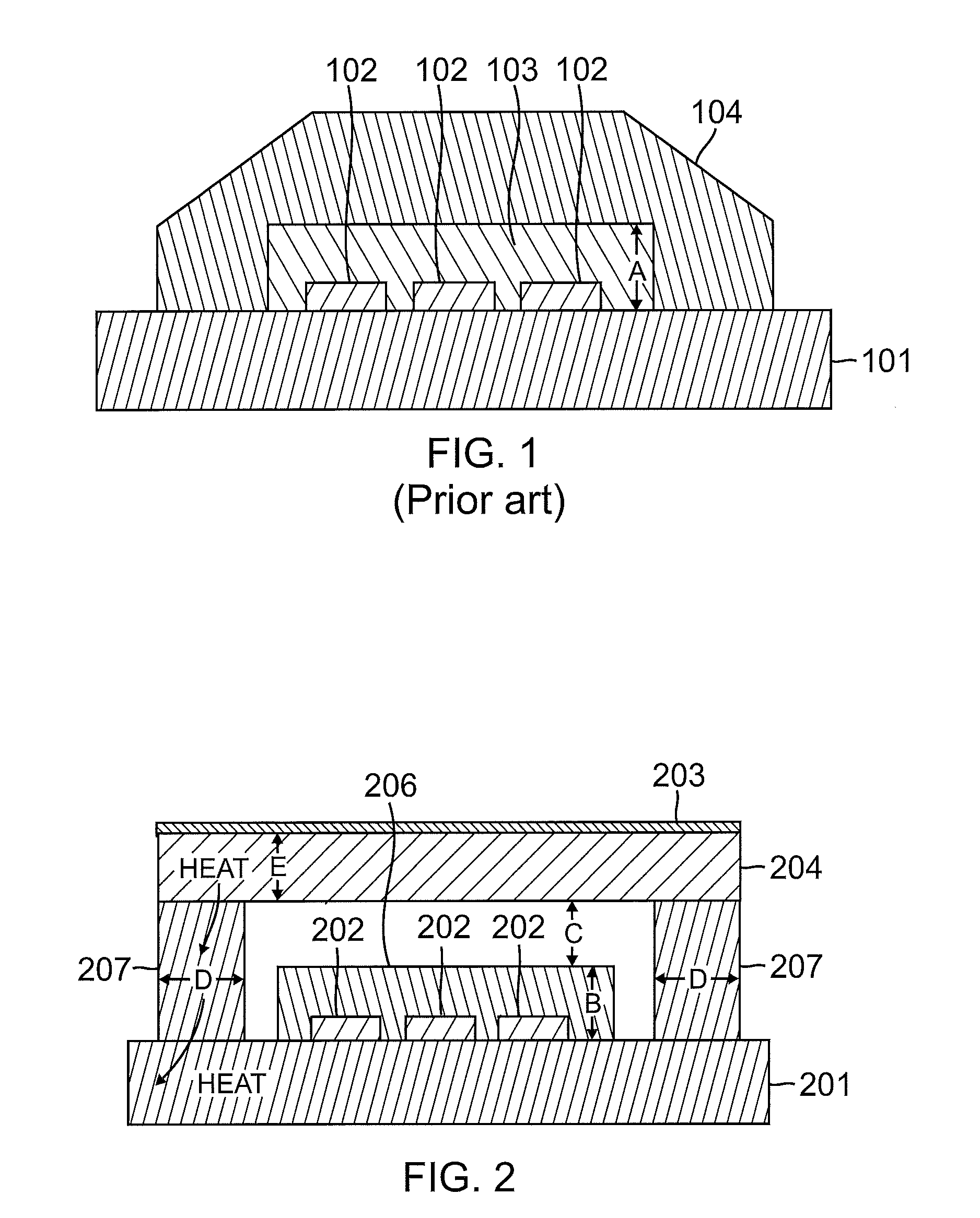
[0008]In accordance with an example of an embodiment, an LED assembly can comprise an LED die, a package configured to at least partially contain the LED die, and means for facilitating heat flow from the LED die to the package and for facilitating the transmission of light from the LED die therethrough (through the means for facilitating heat flow).
[0009]In accordance with an example of an embodiment, an LED assembly can comprise an LED die; a package configured to at least partially contain the LED die; a phosphor configured to absorb a color of light from the LED die and to emit a different color; and means for facilitating heat flow from the phosphor to a package and for facilitating the transmission of light from the LED die therethrough.
[0013]The heat spreader can be configured to conduct heat from the LED junction and the phosphors to the package. By facilitating the removal of heat from the LED, more current can be used to drive the LED. The use of more current facilitates the construction of a brighter LED that can be used in applications such as flashlights, displays, and general illumination. By facilitating the removal of heat from the phosphors, desired colors can be better provided.

Problems solved by technology

However, brighter LEDs require more current and more current results in the production of more heat.
Heat reduces the efficiency of LEDs.
Thus, although contemporary LEDs have proven generally suitable for some purposes, they possess inherent deficiencies that detract from their overall effectiveness and desirability.

Method used


Image

  • Transparent heat spreader for leds
  • Transparent heat spreader for leds
  • Transparent heat spreader for leds

Examples


Embodiment Construction

[0029]As discussed above, the heat produced by current flow through a light emitting diode (LED) must be accommodated, so as to facilitate the use of the higher currents that are required in order to provide brighter LEDs. The temperature Tj of the junction or active area of an LED must typically be kept below approximately 150° C. in order for the LED to produce light efficiently.

[0030]The temperature of any phosphors that are used to modify the color of light for the LED must be as low as possible, so provide desired color conversion efficiency. As those skilled in the art will appreciate, the Stokes shift tends to cause the phosphors of an LED assembly to undesirably heat up. The Stokes shift is the difference in the energy levels between the absorption spectra and the emission spectra of a fluorescent material. Since more energy is absorbed as visible light than is emitted as visible light, the difference in energy becomes heat.

[0031]As the color conversion efficiency of an LED ...


PUM


Abstract

A heat spreader for an LED can include a thermally conductive and optically transparent member. The bottom side of the heat spreader can be configured to attach to a light emitting side of the LED. The top and / or bottom surface of the heat spreader can have a phosphor layer formed thereon. The heat spreader can be configured to conduct heat from the LED to a package. The heat spreader can be configured to conduct heat from the phosphors to the package. By facilitating the removal of heat from the LED and phosphors, more current can be used to drive the LED. The use of more current facilitates the construction of a brighter LED, which can be used in applications such as flashlights, displays, and general illumination. By facilitating the removal of heat from the phosphors, desired colors can be better provided.

Description

TECHNICAL FIELD[0001]The present invention relates generally to light emitting diodes (LEDs). The present invention relates more particularly to a heat sink base for enhancing the optical performance of a LED by reducing the temperature of a junction of the LED and / or by reducing the temperature of one or more phosphors of the LED.BACKGROUND[0002]Light emitting diodes (LEDs) are well known. LEDs are commonly used as indicators on electronic devices. For example, the red or green power indicator on many consumer electronic devices, such as CD and DVD players, is often an LED.[0003]There is a desire to use LEDs in applications such as flashlights, displays, and general illumination. Brighter LEDs are generally required in such applications. However, brighter LEDs require more current and more current results in the production of more heat. Heat reduces the efficiency of LEDs.[0004]Thus, although contemporary LEDs have proven generally suitable for some purposes, they possess inherent ...

Claims


Application Information

Patent Timeline
Patent Type & Authority Applications(United States)
IPC IPC(8): H01L33/00F21V29/00
CPCH01L25/0753H01L33/38H01L33/507H01L33/58H01L33/62H01L2924/0002H01L33/642H01L33/644H01L2924/00
Inventor SHI, WEI
Owner BRIDGELUX INC
Why Eureka
Try Eureka