Braking energy recovery system for a vehicle and vehicle equipped with same

Active Publication Date: 2010-06-10
DEV EFFENCO INC +1
View PDF18 Cites 56 Cited by
  • Summary
  • Abstract
  • Description
  • Claims
  • Application Information

AI Technical Summary

Benefits of technology

[0010]It is an object of the present invention to provide a braking energy recovery system that overcomes or mitig

Problems solved by technology

Indeed, the typical duty cycle of a refuse truck in collection mode is characterized by a high frequency of stop and go cycles and a low average speed.
Furthermore, the energy consumption required by the frequent use of hydraulic auxiliary systems, such as the garbage compactor, is very high, reaching close to 40% in collection mode.
Systems for assisting the vehicles during re-launch are however rather complex as

Method used


Image

  • Braking energy recovery system for a vehicle and vehicle equipped with same
  • Braking energy recovery system for a vehicle and vehicle equipped with same
  • Braking energy recovery system for a vehicle and vehicle equipped with same

Examples


Embodiment Construction

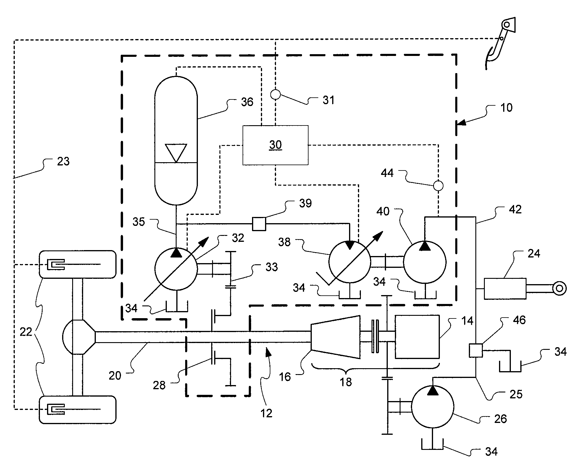
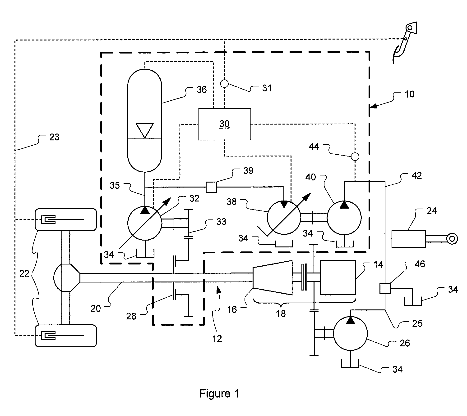
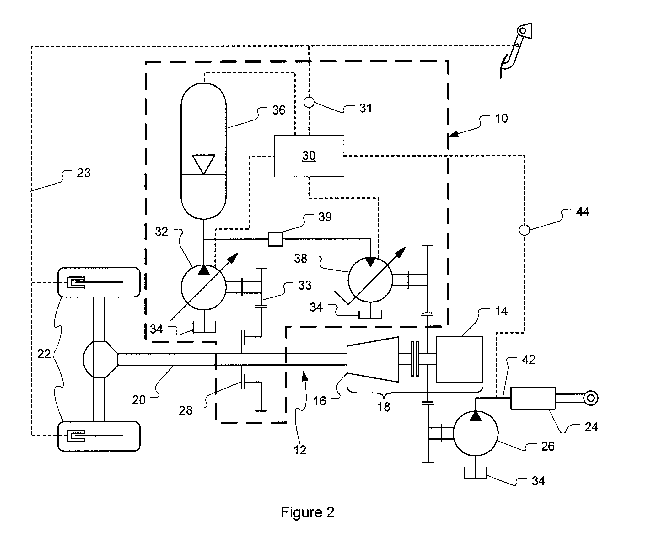
[0018]The present invention relates to a braking energy recovery system that may be provided as standard equipment on new vehicles as well as retrofitted to existing vehicles. Through the use of variable displacement hydraulic pump and motor, it is possible to modulate the energy recovered as a function of a braking demand and to modulate the energy restored as a function of a power demand from an auxiliary system. Moreover, in one embodiment of the invention, the braking energy recovery system may also be used for assisting the vehicle during acceleration.

[0019]FIG. 1, now referred to, schematically depicts the braking energy recovery system 10 of the present invention. For a better understanding, the braking energy recovery system 10 is shown installed on a powertrain 12 of a vehicle. The components of the powertrain 12 shown in FIG. 1 are an internal combustion engine 14 and a transmission 16, together forming an engine-transmission assembly 18, and a driveshaft 20 connecting a w...


PUM


Abstract

A braking energy recovery system adapted for use on a vehicle and a vehicle having such a system installed. The vehicle has an engine-transmission assembly, a driveshaft, a braking system and an auxiliary system. The energy recovery system comprises a first pump, a hydraulic accumulator and a hydraulic motor. The first pump is a variable displacement hydraulic pump. The hydraulic accumulator is connected to the first pump and is operative to store hydraulic fluid under pressure. The hydraulic motor is hydraulically connected to the accumulator to receive hydraulic fluid. The motor is adapted to drive a second hydraulic pump, which is hydraulically connected to the auxiliary system, using hydraulic energy stored in the accumulator.

Description

FIELD OF THE INVENTION[0001]The present invention generally relates to the field of energy efficiency in vehicles. More specifically, the present invention relates to a braking energy recovery system for use on vehicles having auxiliary systems, the energy recovery system being able to power at least partially the auxiliary systems.BACKGROUND OF THE INVENTION[0002]Braking energy recovery systems, also known as hybrid systems, have been known for a while in the field of electric vehicles such as cars and light trucks. In most of these applications, the energy recovered during braking, which would otherwise be dissipated as heat, is reused to drive the vehicle from a stop.[0003]Refuse trucks are very well suited to the application of braking energy recovery systems. Indeed, the typical duty cycle of a refuse truck in collection mode is characterized by a high frequency of stop and go cycles and a low average speed. Furthermore, the energy consumption required by the frequent use of hy...

Claims


Application Information

Patent Timeline
IPC IPC(8): B60T13/70
CPCB60K6/12B60T1/10Y02T10/6208B60Y2200/144B60W10/30B65F3/00F16D61/00B60T10/04Y02W30/10Y02T10/62B60T1/093B60K25/00B60W10/18F16D57/06
Inventor FOUQUET, DANYLACROIX, BENOITARSENAULT, DAVID
Owner DEV EFFENCO INC
Why Eureka
Try Eureka