Fast electrostatic shutter and method of achieving offset compensation in infrared video imagers using fast shutters
- Summary
- Abstract
- Description
- Claims
- Application Information
AI Technical Summary
Benefits of technology
Problems solved by technology
Method used
Image
Examples
embodiment 100
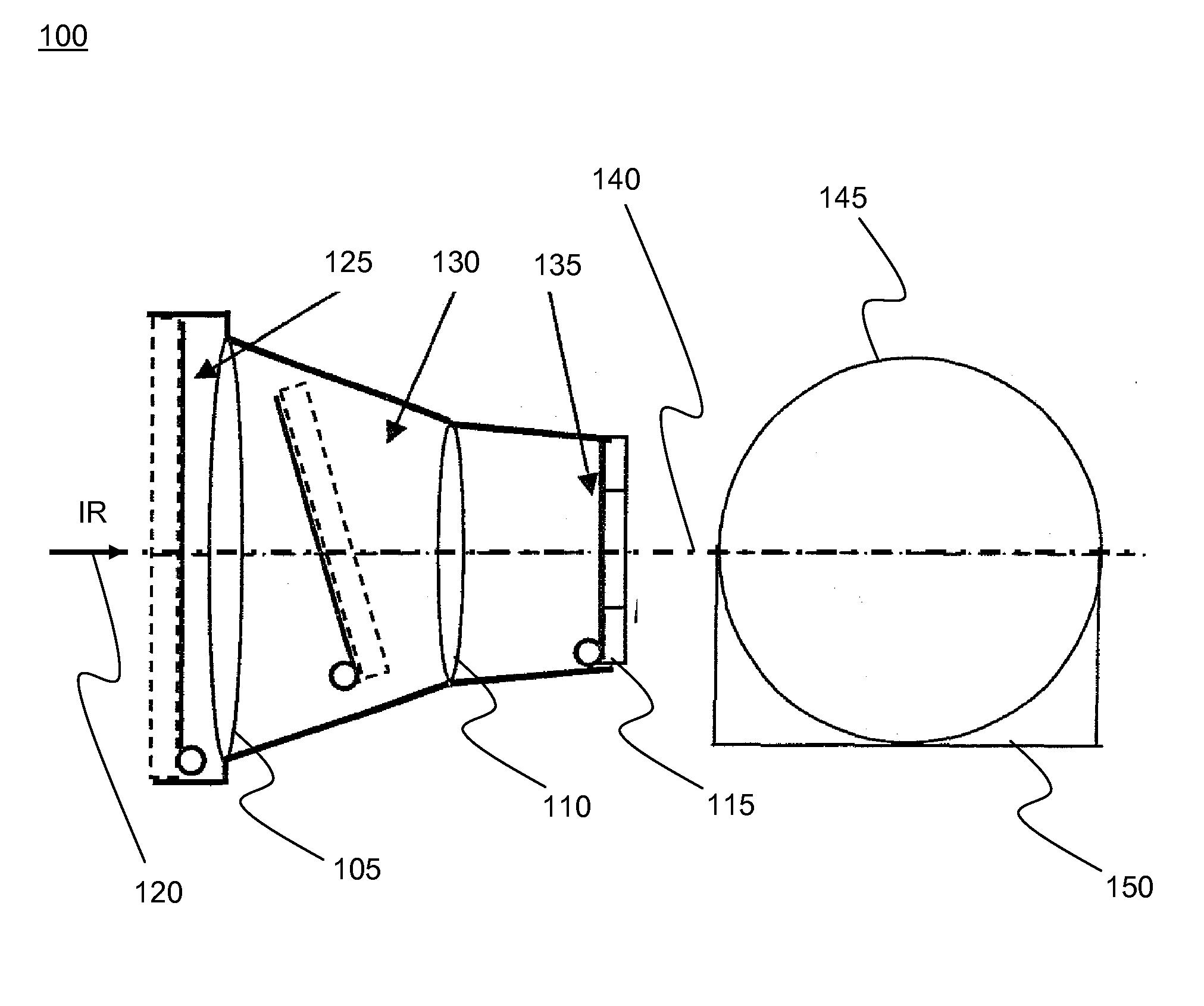
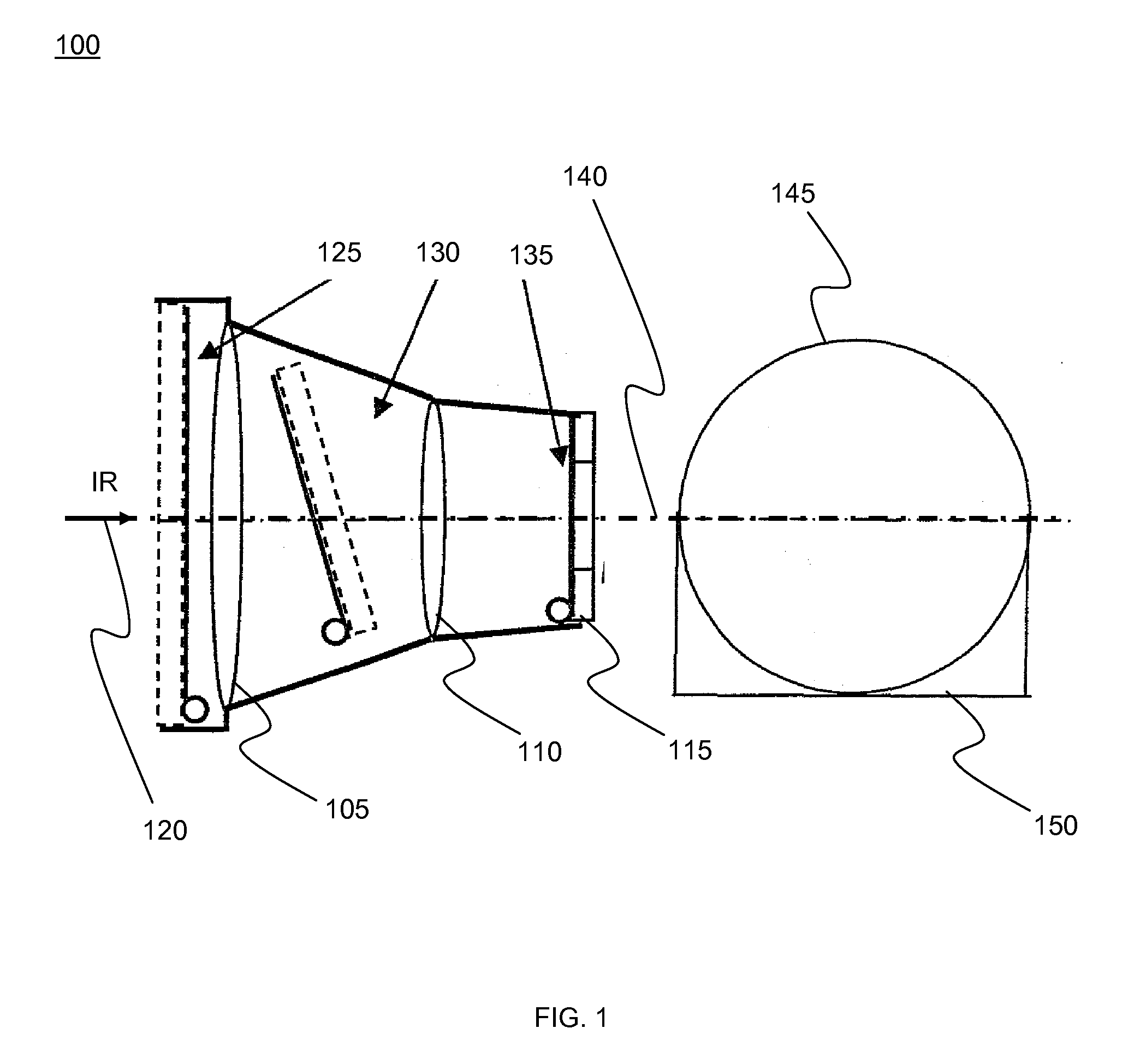
[0020]FIG. 1 depicts a simplified diagram of an imager embodiment 100. The imager diagram shows a first lens 105, a second lens 110, and a focal plane array (imager module) 115. IR arrow 120 denotes the incoming infrared radiation (from the scene). Alternative locations of electrostatic shutters include a location 125 proximate first lens 105, a location 130 between first lens 105 and second lens 110, and a location 135 proximate focal plane array 115. Location 130 depicts a tilted shutter in which the shutter does not reflect the focal plane array (FPA) onto itself. In other embodiments, shutter at location 130 can be perpendicular to optical axis 140. View 145 shows a front perspective of the imager, from the direction of the IR radiation 120, and includes area 150 that accommodates a rolled-up shutter. When the metal / polymer film is manufactured on the inner or the outer surface of the optical window of the focal plane array, the window has an additional role of shutter substrate...
embodiment 200
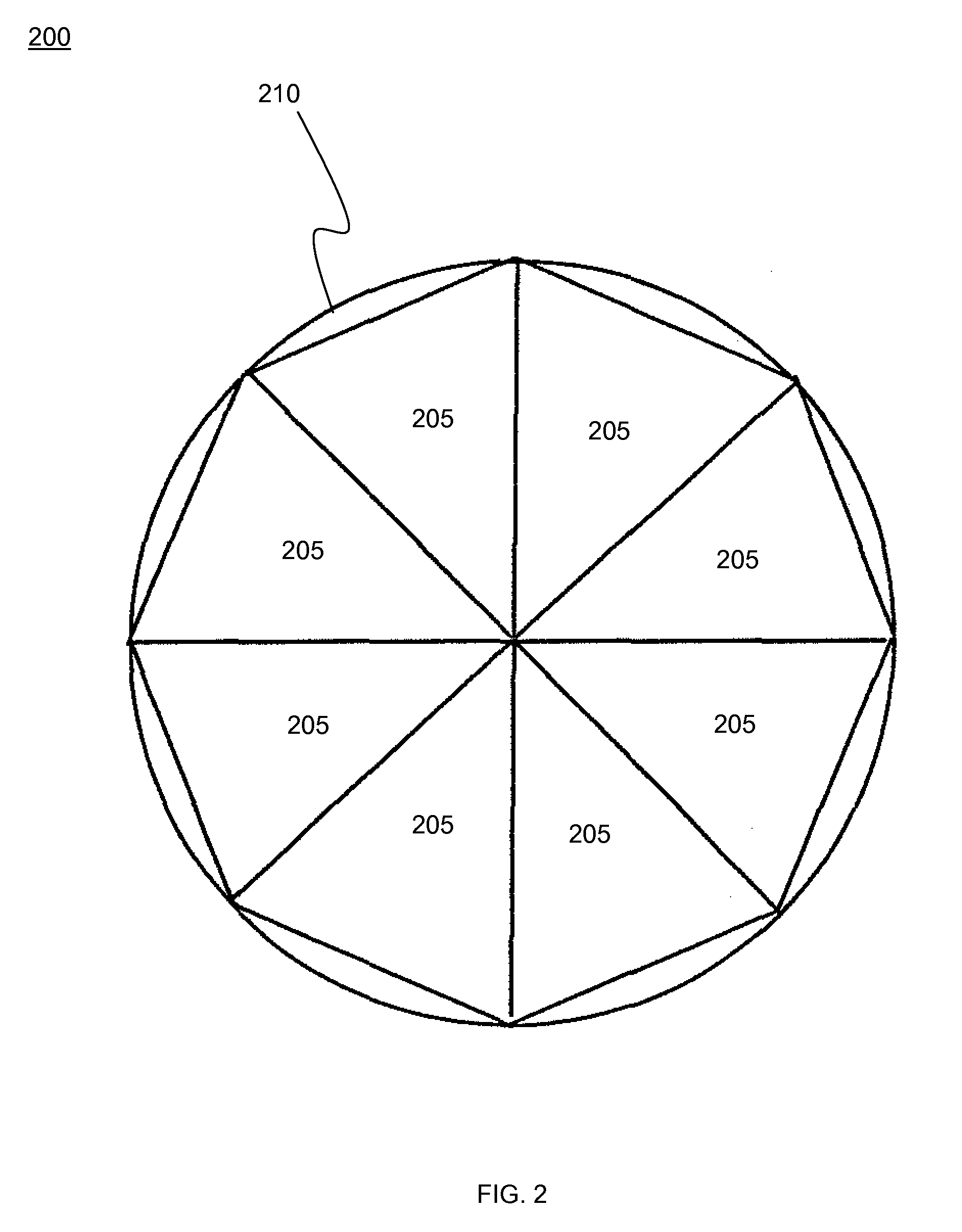
[0021]FIG. 2 depicts a simplified diagram of a segmented shutter embodiment 200. The shutter is delineated into several segments 205, making it possible to manufacture and operate it on a curved substrate (e.g. a lens surface) saving space on edge 210 of the imager, in the area where the shutter rolls up. The individual segments (petals) deploy simultaneously. This saves space along the perimeter of the optical elements, the area that otherwise would be required to accommodate the rolled-up shutter. As mentioned, if the petals are narrow enough, such composite shutter may be manufactured on a curved surface of a lens, thus reducing size, weight, cost and the number of optical interfaces.
[0022]FIG. 3 depicts a simplified diagram of a front view of an assembly embodiment 300 containing multiple shutters or apertures. Three shutters 305, 310, and 315 are shown rolled up; one 320—forming a small aperture 325—is unrolled. Here, several shutters are manufactured on the same substrate and ...
embodiment 400
[0023]FIG. 4 depicts a simplified diagram of a shutter embodiment 400 including a thermal uniformity component. Rolled-up shutter 405 touching a metal bar 410 results in better thermal uniformity of the shutter. Outline 415 depicts a circular extent of a rolled-out shutter. Because the shutter contains a very thin metal layer, thermal conductivity along its roll-up axis (along the glue stripe) may be insufficient for a uniform temperature. In order to overcome this, a thermally conductive component such as a metal bar can be positioned along the edge of the optical system. Any thermally conductive component can be used in embodiments. When the shutter is in the rolled-up position (due to stress forces) it is pressed against the thermally conductive component. This component serves as a thermal shunt for the shutter. Since, during the imager operation, the shutter is rolled up most of the time, it will be in contact with the bar. As a result, shutter temperature will be uniform.
[0024...
PUM
 Abstract
Description
Claims
Application Information
 - R&D
- Intellectual Property
- Life Sciences
- Materials
- Tech Scout
- Unparalleled Data Quality
- Higher Quality Content
- 60% Fewer Hallucinations
Browse by: Latest US Patents, China's latest patents, Technical Efficacy Thesaurus, Application Domain, Technology Topic, Popular Technical Reports.
© 2025 PatSnap. All rights reserved.Legal|Privacy policy|Modern Slavery Act Transparency Statement|Sitemap|About US| Contact US: help@patsnap.com


