Radial compressor

a compressor and radial technology, applied in the direction of machines/engines, stators, liquid fuel engines, etc., can solve the problems of narrow flow rate range between the surge flow rate and the choke flow rate, and the inability to perform stable operation at a surge flow rate or less, so as to reduce the pressure in the recirculation passage, reduce the inlet pressure of the recirculation passage, and run easily

Active Publication Date: 2010-06-10
MITSUBISHI HEAVY IND LTD
View PDF5 Cites 13 Cited by
  • Summary
  • Abstract
  • Description
  • Claims
  • Application Information

AI Technical Summary

Benefits of technology

[0041]Thus, according to the invention described above, the stagnant pressure at the inlet of the recirculation passage is reduced, allowing a flow to easily run into the recirculation passage, and the effect for reducing the pressure in the recirculation passage is obtained with resultant improved recirculation efficiency.

Problems solved by technology

However, the range of flow rate permitting the stable operation is limited, so that it is necessary to operate the radial compressor 100 at a low-efficiency operating point away from a surge flow rate so as not to induce surging during a transient change at a rapid acceleration.
The radial compressor 100 presents a significant drawback in that the flow rate range between the choke flow rate and the surge flow rate becomes narrow, as illustrated in FIG. 10(B), due to the occurrence of the surging.
As illustrated in FIG. 10(B), the stable operation is performed according to the relationship between the choke flow rate and the surge flow rate; however, the stable operation cannot be performed at a flow rate of the surge flow rate or less.
This poses a drawback in that performance deteriorates at a normal operating point.

Method used


Image

  • Radial compressor
  • Radial compressor
  • Radial compressor

Examples


first embodiment

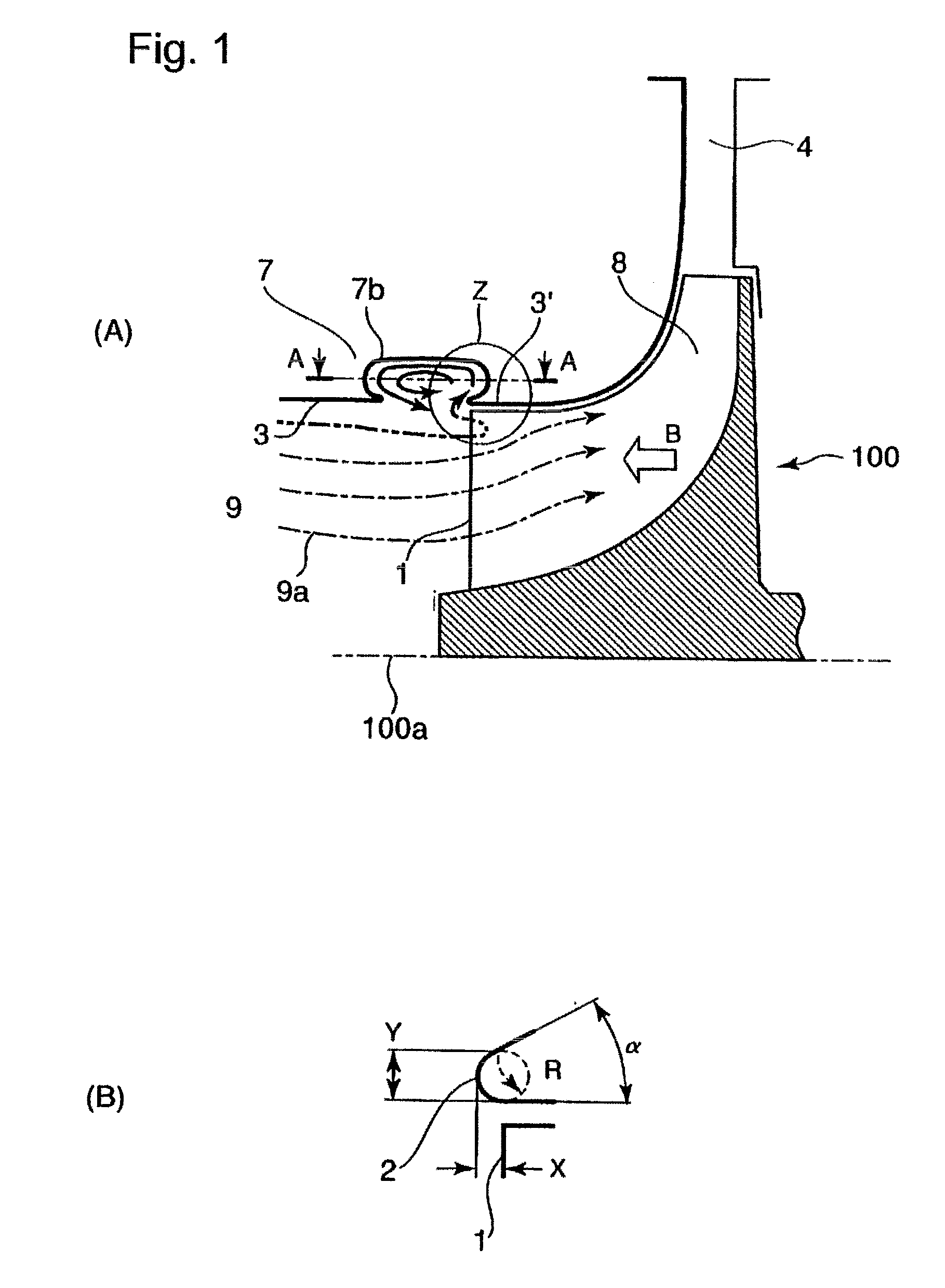
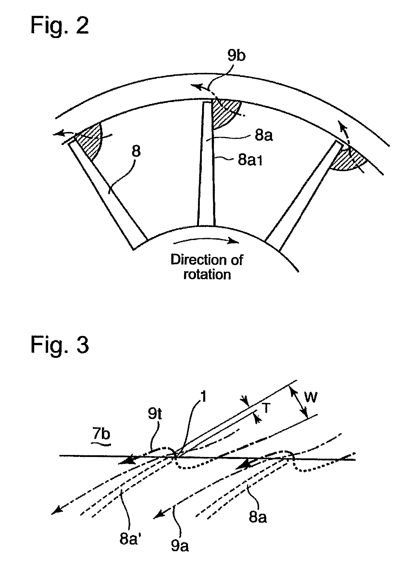
[0053]FIG. 1(A) is a sectional view of an essential section of a radial compressor of an exhaust turbo-charger according to a first embodiment of the present invention, and FIG. 1(B) is an enlarged view of portion Z in FIG. 1(A). FIG. 2 is a fragmentary view taken at line B-B in FIG. 1(A), and FIG. 3 is a fragmentary view taken at line A-A in FIG. 1(A).

[0054]In FIGS. 1 to 3, reference numeral 7 denotes a compressor housing in which an impeller 8 is accommodated, reference numeral 9 denotes an air inlet passage of the compressor housing 7, and reference numeral 4 denotes a diffuser. These components constitute a radial compressor 100. Further, reference numeral 100a denotes a rotational axial center of an exhaust turbo-charger.

[0055]An annular concave groove 7b having an elliptical section is formed in a housing peripheral wall 3 of the air inlet passage 9 of the compressor housing 7, and an opening rear end portion 2 of the annular concave groove 7b which meets the housing periphera...

second embodiment

[0072]Further, FIG. 4 is a sectional view of an essential section of a radial compressor of an exhaust turbo-charger according to a second embodiment. In the second embodiment, a housing peripheral wall 3 in communication with the aforesaid annular concave groove 7b is formed into a curved surface having a radius R. The rest of the construction is the same as the construction of the aforesaid first embodiment, and the same components as those in the first embodiment are assigned the same reference numerals.

third embodiment

[0073]FIG. 5 is a sectional view of an essential section of a radial compressor of an exhaust turbo-charger according to a third embodiment.

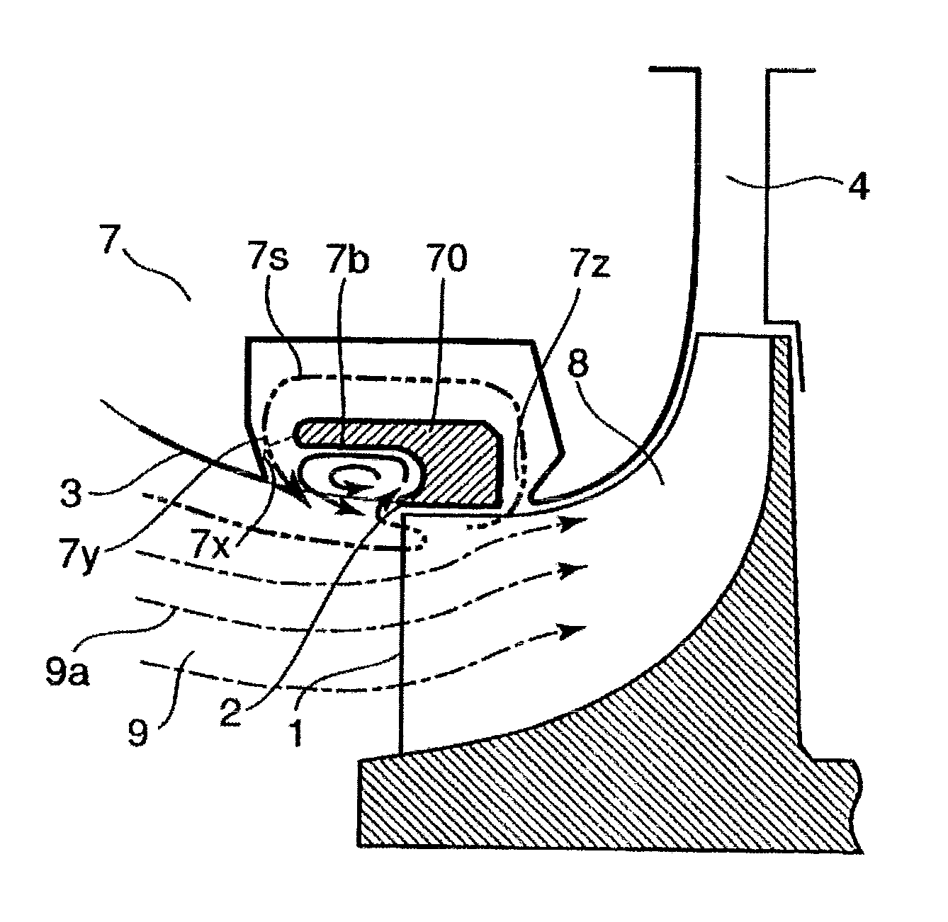
[0074]The third embodiment of the present invention has an opening 7z at a middle between a blade front end surface 1 of an impeller 8 and an impeller outlet, and an opening 7y at an upstream side from the blade front end surface 1 of the impeller 8, and includes a recirculation passage 7s which brings the two openings 7z and 7y in communication. Further, an annular component 70 is installed inside the recirculation passage 7s so as to be able to form the recirculation passage 7s. Inside the annular component 70, an annular concave groove 7b and an upstream end wall 7x (the virtual line indicated by the dashed line in the figure) thereof are formed such that they share an upstream-side wall surface of the opening 7y on the upstream side of the impeller of the recirculation passage 7s.

[0075]More specifically, a housing peripheral wall 3 of an ai...


PUM


Abstract

A radial compressor is capable of preventing the occurrence of separation caused by a flow which goes beyond the front end of a blade and turns onto a negative pressure plane from a pressure plane, thereby reducing a surging flow rate to a smaller flow rate. The radial compressor includes an impeller which is rotatively driven, axially introduces air taken in through an air inlet passage formed in a housing, pressurizes the introduced air, and discharges the pressurized air in a radial direction, wherein an annular concave groove is formed in a peripheral wall of the air inlet passage of the housing, a rear end portion of an opening of the annular concave groove, which rear end portion meets the housing peripheral wall, is provided in the vicinity of a blade front end surface of the impeller, and the rear end portion of the opening of the annular concave groove is formed such that an axial projecting amount X thereof relative to the blade front end surface of the impeller is set to −1T≦X≦1.5T (where T denotes the thickness of the distal portion of a blade).

Description

TECHNICAL FIELD [0001]The present invention relates to a radial compressor which is used with a pneumatic device or the like of a compressor of an exhaust turbo-charger of an internal combustion engine, and provided with an impeller which is rotatively driven to axially introduce air taken in through an air passage formed in a housing and which pressurizes the introduced air, then discharges the pressurized air in the radial direction, wherein an annular concave groove is formed in the peripheral wall of the air passage of the housing and an opening rear end portion of the annular concave groove which meets the housing peripheral wall of the annular concave groove is provided in the vicinity of a front end surface of a blade of the impeller.BACKGROUND ART [0002]FIG. 6 is a sectional view along a rotational axis line illustrating a conventional example of a radial-flow type exhaust turbo-charger with the aforesaid radial compressor built therein.[0003]Referring to FIG. 6, reference n...

Claims


Application Information

Patent Timeline
Patent Type & Authority Applications(United States)
IPC IPC(8): F04D27/02F04D29/42
CPCF04D29/4213F04D29/685F04D29/441F05D2220/40F05D2250/51F04D29/44F04D29/66
Inventor HIGASHIMORI, HIROTAKASUGIMOTO, KOICHIISOBE, HIDEYOSHISHIRAISHI, TAKASHI
Owner MITSUBISHI HEAVY IND LTD
Why Eureka
Try Eureka