Wind turbine yaw bearing determination

a technology of wind turbines and bearings, applied in the direction of liquid fuel engines, vessel construction, marine propulsion, etc., can solve the problems of reducing the accuracy of the wind direction that is sensed, the absolute yaw position reference point can drift over time, and the current bearing of the nacelle may not be known with sufficient accuracy

Inactive Publication Date: 2010-06-10
GENERAL ELECTRIC CO
View PDF15 Cites 18 Cited by
  • Summary
  • Abstract
  • Description
  • Claims
  • Application Information

AI Technical Summary

Problems solved by technology

However, turbulent airflow caused by the blades 10 can decrease the accuracy of the wind direction that is sensed by the anemometer 18.
In addition, even when the wind direction can be accurately determined, the current bearing of the nacelle may not be known with sufficient accuracy in order to precisely reposition blades into the next yaw bearing.
This problem arises because the initial “absolute” yaw position of the nacelle 6 is typical...

Method used


Image

  • Wind turbine yaw bearing determination
  • Wind turbine yaw bearing determination
  • Wind turbine yaw bearing determination

Examples


Embodiment Construction

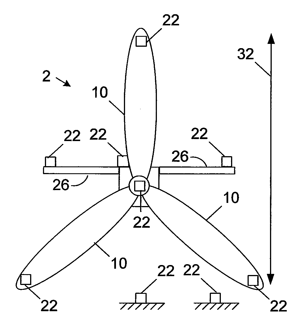
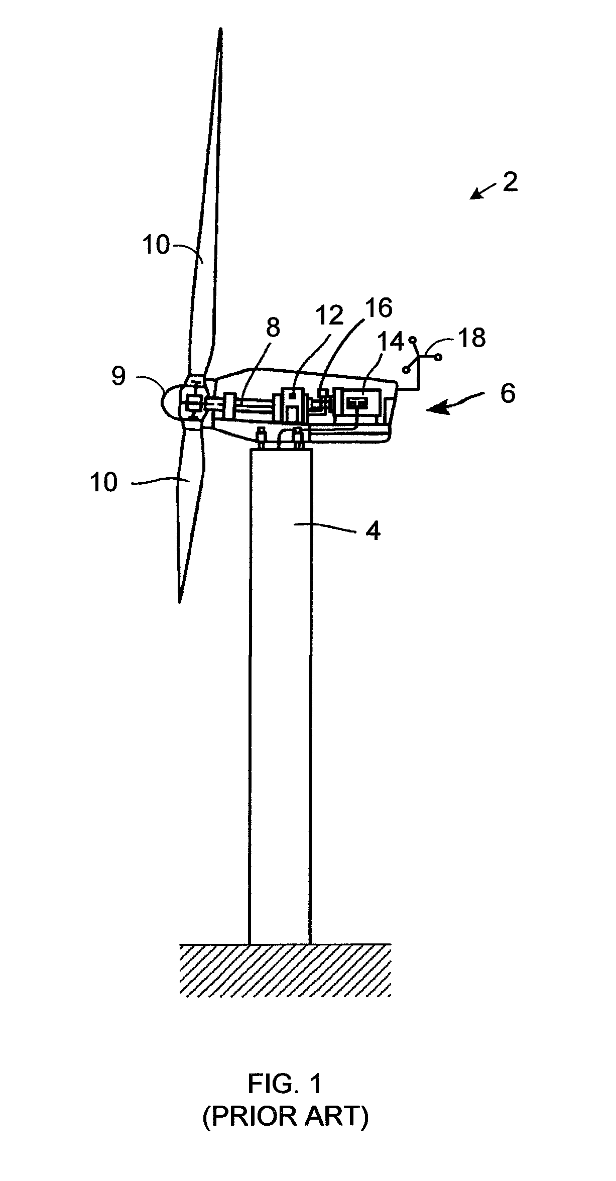
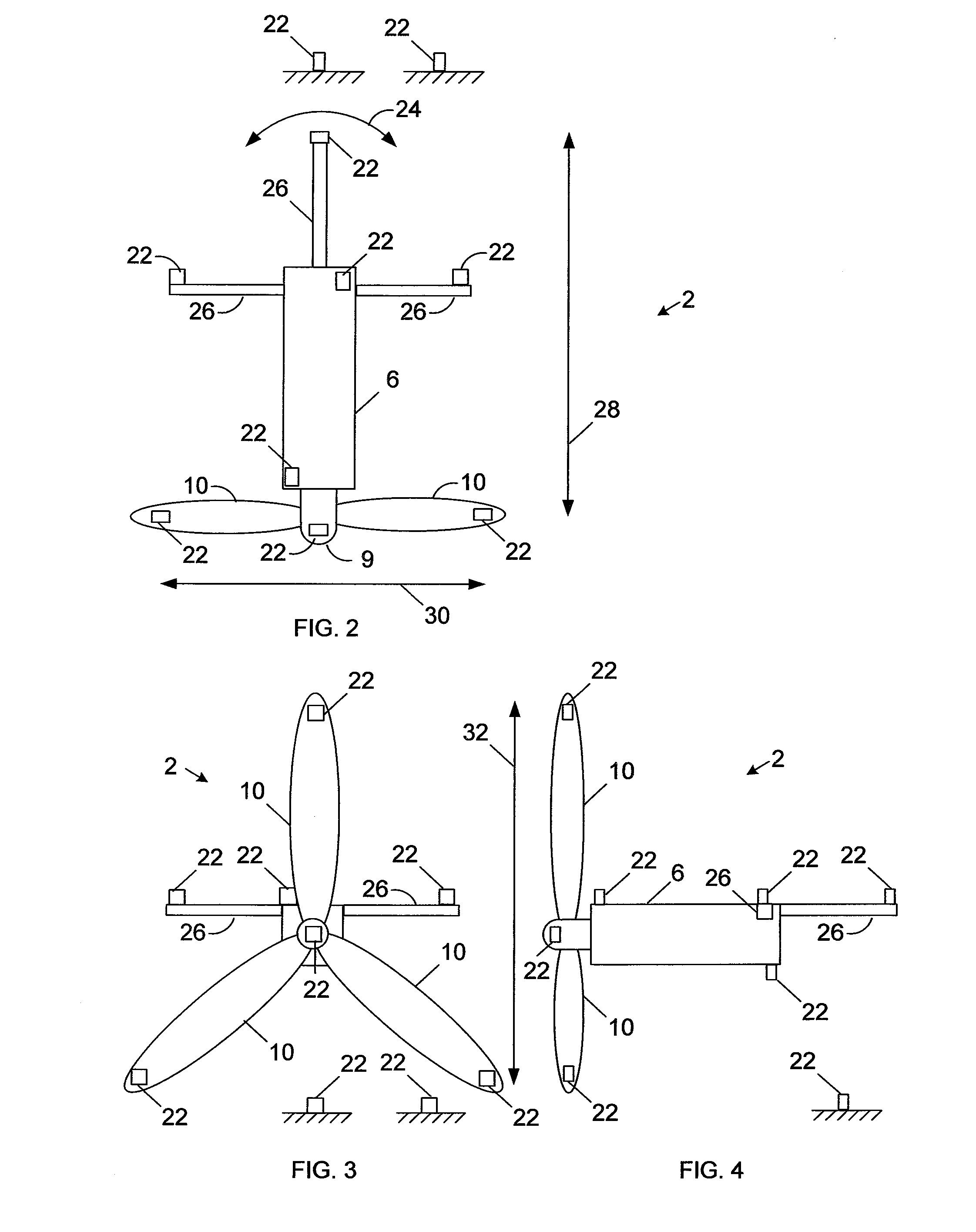
[0015]FIGS. 2, 3, and 4 are schematic top, front, and side views, respectively, of a wind turbine system having one or more position sensors 22 for use with the wind turbine 2 shown in FIG. 1. However, the technology describe here may also be used with any other wind turbine.

[0016]One or more of the position sensors 22 may include, but is not limited to, a global position sensor for determining vertical and / or horizontal position using the Global Positioning System of global navigation satellites including any of the various augmentation systems, such as Assisted GPS, Differential GPS (e.g., OmiSTAR, StarFire, DGPS, NDGPS), Inertial Navigation Systems, Wide Area Augmentation System, Satellite Band Augmentation System, European Geostationary Navigation Overlay Service, and / or Multi Satellite Augmentation System. Some or all of the position sensors 22 may be arranged at various locations, including but not limited to those illustrated hear, for determining position(s) indicative of a ...


PUM


Abstract

A wind turbine includes a sensor for determining a position indicative of a yaw bearing of the wind turbine.

Description

CROSS REFERENCE TO RELATED APPLICATIONS[0001]The subject matter disclosed here is generally related to commonly-owned, copending U.S. patent application Ser. No. ______ (Attorney Docket No. 233934) for “Wind Turbine with GPS Load Control” by Pedro Benito et al filed concurrently with this application.BACKGROUND OF THE INVENTION[0002]1. Technical Field The subject matter described here generally relates to wind turbines, and, more particularly, to determining yaw bearing using positioning systems.[0003]2. Related Art[0004]A wind turbine is a machine for converting the kinetic energy in wind into mechanical energy. If the mechanical energy is used directly by the machinery, such as to pump water or to grind wheat, then the wind turbine may be referred to as a windmill. Similarly, if the mechanical energy is converted to electricity, then the machine may also be referred to as a wind generator or wind power plant.[0005]Wind turbines are typically categorized according to the vertical o...

Claims


Application Information

Patent Timeline
IPC IPC(8): F03D11/00
CPCF03D7/0204Y02E10/723F05B2270/329F05B2260/80Y02E10/72
Inventor MCCORKENDALE, TIMOTHY E.
Owner GENERAL ELECTRIC CO
Why Eureka
Try Eureka