Power supply device, power cable, and reception device

a power supply device and power cable technology, applied in the direction of cables, insulated conductors, protective materials radiating elements, etc., can solve the problems of insufficient wide frequency band and gain, inability to readily receive broadcast waves indoors, and marked deterioration of sensitivity, so as to achieve sufficient wide frequency band, sufficient gain, and sufficient portability of antennas

Inactive Publication Date: 2010-06-10
SONY CORP
View PDF3 Cites 3 Cited by
  • Summary
  • Abstract
  • Description
  • Claims
  • Application Information

AI Technical Summary

Benefits of technology

[0036]According to the above configurations, portability regarding antennas can be improved sufficiently, and bro

Problems solved by technology

Note however, broadcast waves have are not readily received indoors due to various types of shielding objects.
Accordingly, sensitivity is markedly deteriorated in the case of receiving broadcast

Method used


Image

  • Power supply device, power cable, and reception device
  • Power supply device, power cable, and reception device
  • Power supply device, power cable, and reception device

Examples


sixth embodiment

6. Sixth Embodiment

[0210]FIG. 43 is a diagram illustrating the configurations and connection relationship of the principal portions of the reception system according to a sixth embodiment of the present invention in detail in contrast with FIG. 35. With the reception system 81 in FIG. 43, the length of the power transmission cable 44 is set to a certain length L1, and the ferrite core 74 is disposed on the power supply unit 6 side end of the power transmission cable 44. Also, the core cables LL and LG are connected to the power supply circuit 16 via the inductors 17L and 17G.

[0211]Thus, the reception system 81 doubly prevents the entry of noise or a high-frequency signal on the power supply unit 6 side by the ferrite core 74 and the inductors 17L and 17G. Accordingly, influence of power supply noise of a frequency of 30 MHz or less can be reduced markedly.

[0212]With the present sixth embodiment, the ferrite core and the inductors are disposed on the power supply unit side, whereby t...

seventh embodiment

7. Seventh Embodiment

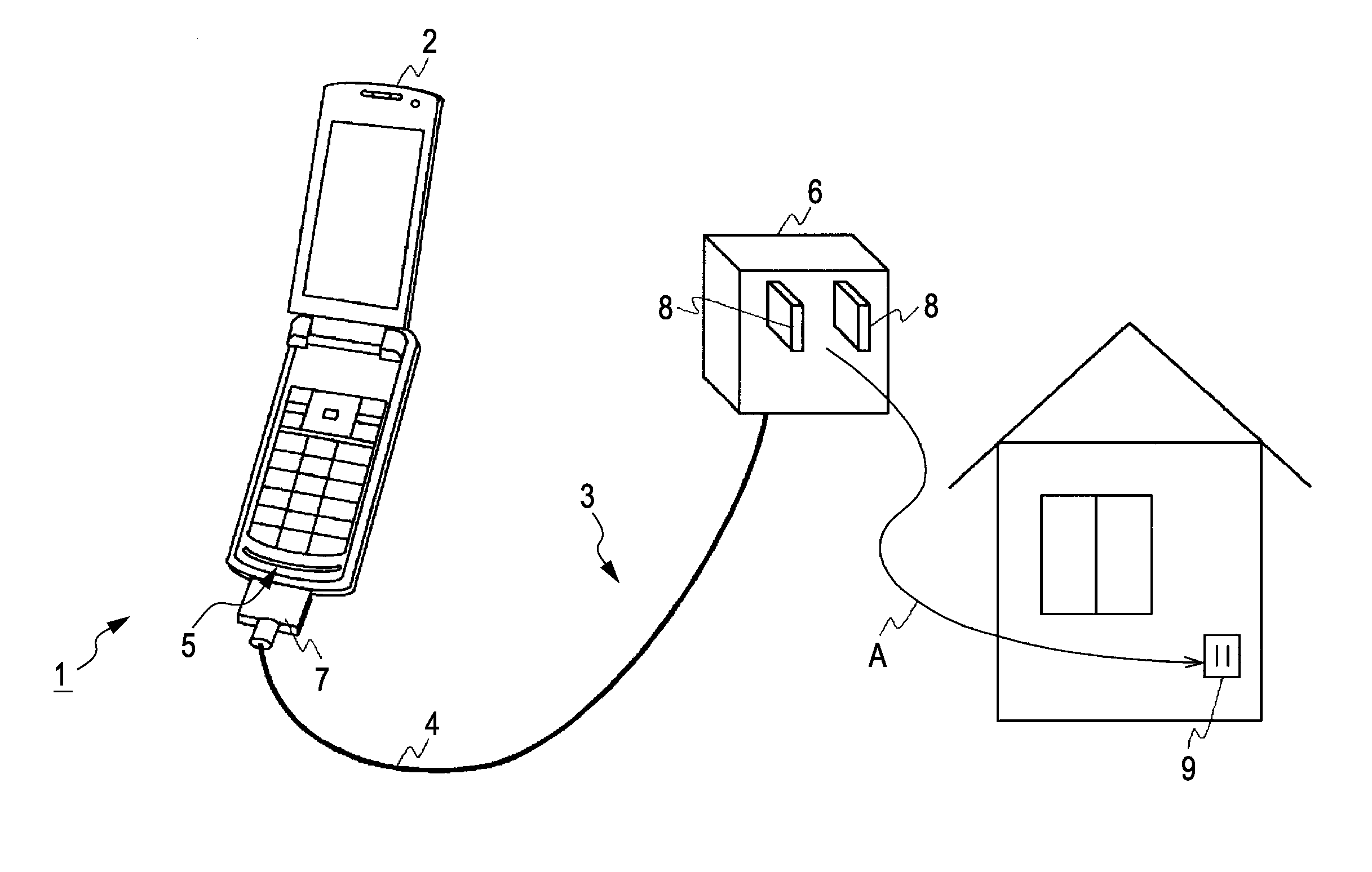
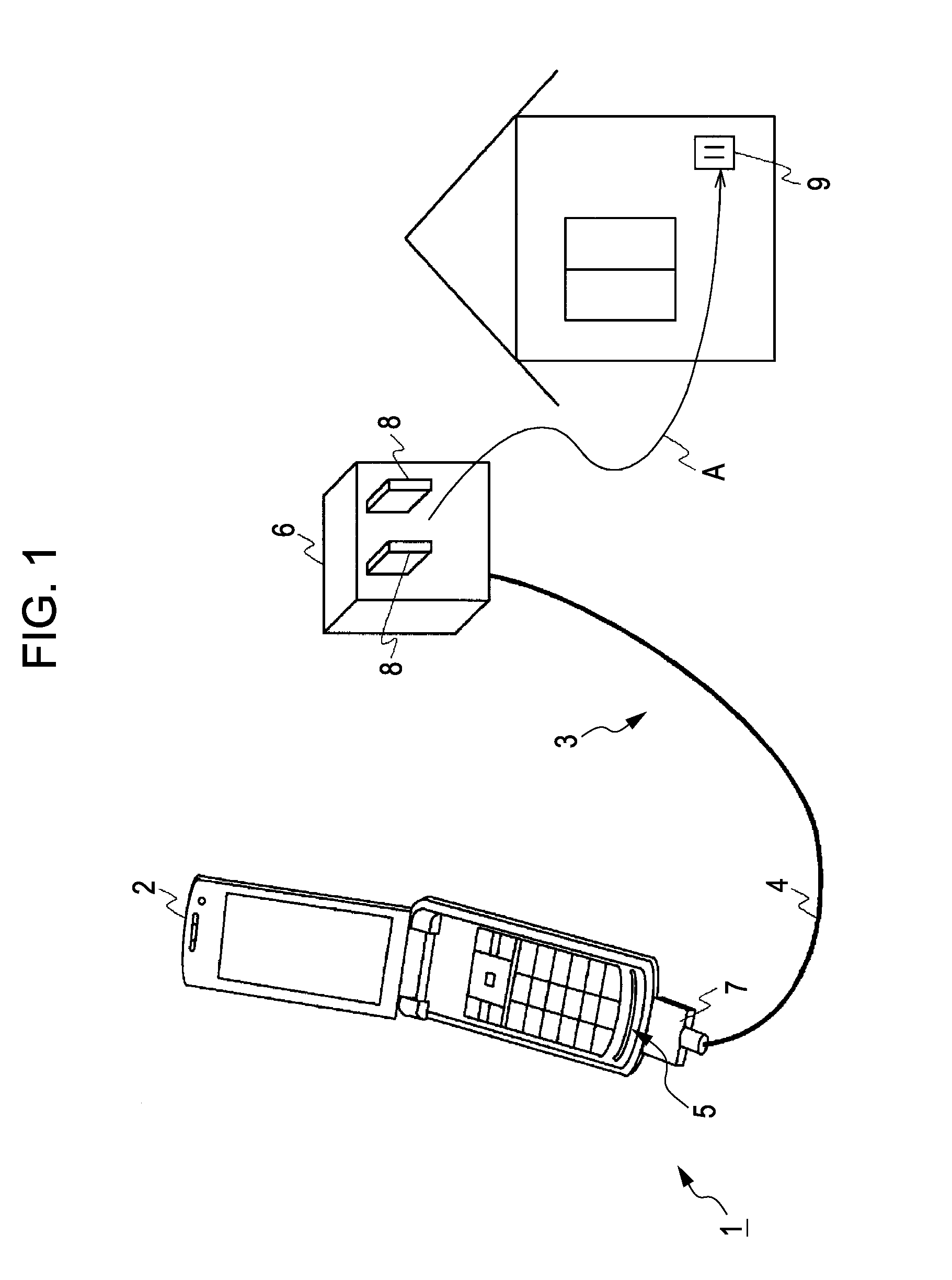
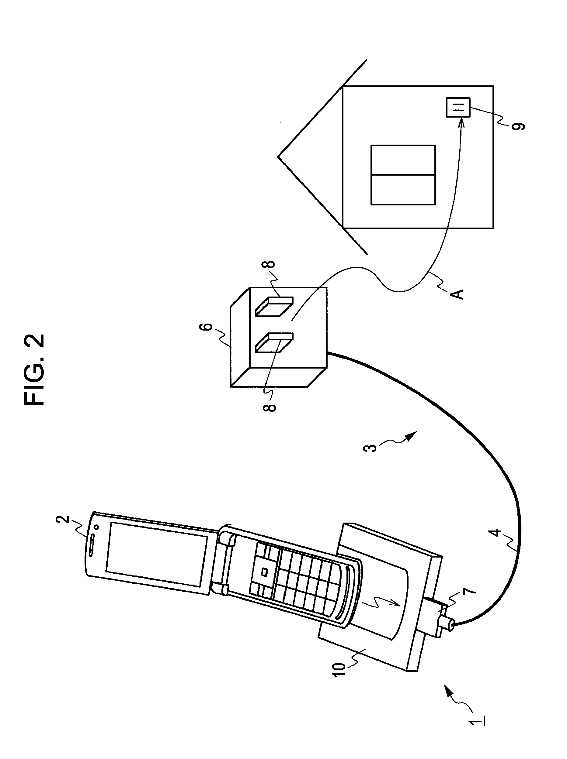
[0213]With the present seventh embodiment, the power generated at a power supply device is transmitted to a cellular phone via a relay cable. With the relay cable, connectors for connecting both ends of the power transmission cable and the connectors 5 and 7 are provided.

[0214]With the present seventh embodiment, the arrangement relating to the power transmission cable according to each of the above embodiments is applied to this relay cable, and thus, the relay cable is controlled to serve as an antenna.

[0215]According to the present seventh embodiment, even in the event that the power generated at a power supply device is transmitted to a cellular phone via a relay cable, the arrangement of each of the above embodiments is applied to this relay cable, and the relay cable is controlled to serve as an antenna, the same advantages as each of the above embodiments can be obtained.

eighth embodiment

8. Eighth Embodiment

[0216]With the present eighth embodiment, an amplifying circuit is disposed on the wiring board 19 provided to the connector 7, where a high-frequency signal induced at a portion serving as an antenna is amplified, and is output to a cellular phone. The present eighth embodiment is configured in the same way as the above embodiments except that the arrangement relating to this amplifying circuit differs.

[0217]With the present embodiment, a high-frequency signal is amplified at the amplifying circuit, whereby sensitivity is improved markedly, and the same advantages as each of the above embodiments can be obtained.


PUM


Abstract

A power supply device includes: a power supply unit configured to output the power of a mainframe; and a power transmission cable configured to supply the power output from the power supply unit to the mainframe via a connector; with the power transmission cable including a mainframe side high-frequency cutoff portion disposed between the power supply terminal of the connector, a power supply unit side high-frequency cutoff portion, which is disposed on the power supply unit side at a predetermined length from the connector, configured to restrict the length of a portion serving as an antenna, a first transmission line used for power supply to the mainframe via the mainframe side high-frequency cutoff portion, and a second transmission line to be connected to a tuner of the mainframe via the connector.

Description

BACKGROUND OF THE INVENTION[0001]1. Field of the Invention[0002]The present invention relates to a power supply device, a power cable, and a reception device, which can be applied to electronic equipment such as a cellular phone, a television receiver, or the like which can receive broadcast waves.[0003]2. Description of the Related Art[0004]In general, cellular phones capable of receiving digital television broadcasting or the like receive broadcast waves at a built-in antenna or external antenna. Built-in antennas have an advantage in that the appearance of the cellular phone is not ruined due to an unsightly antenna, but have a drawback in being inferior to external antennas regarding sensitivity, and tend to be influenced by internal noise.[0005]On the other hand, examples of external antennas include rod antennas. Rod antennas have a feature of excellent sensitivity or the like as compared to built-in antennas, but have drawbacks such as ruining the appearance of the cellular p...

Claims


Application Information

Patent Timeline
IPC IPC(8): H04B1/18H01Q1/00H01Q9/16H01B7/00H01Q5/10
CPCH01Q1/242H01Q1/40H01Q1/46H01Q5/321H01Q21/30H04M19/08H01Q5/00
Inventor YOSHINO, YOSHITAKAKOMORI, CHISATOMUKAI, KOICHI
Owner SONY CORP
Why Eureka
Try Eureka