
Lancing Device For Minimizing Pain

a technology of lancets and minimizing pain, applied in the field of lancets, can solve the problems of user pain, unpredictable needle trajectory, and excessive impact vibration, and achieve the effects of minimizing pain to the user, minimizing or eliminating pitching or vibration of the lancet, and minimizing or eliminating noise produced

Inactive Publication Date: 2010-06-10
VENTURE CORP LTD
View PDF2 Cites 84 Cited by
  • Summary
  • Abstract
  • Description
  • Claims
  • Application Information

AI Technical Summary

Benefits of technology

"The present invention is a lancing device that minimizes pain while withdrawing sample fluid. It includes a lancet, a housing with leaf springs and guides for smooth lancing, a probe with a cam profile for controlling the lancet speed, a gear-damper system for reducing noise, and a priming system. The guides can be v-shaped or profile guides and are used with leaf springs to prevent probe movement. The probe with cam profile can have slotted guides or a torsion spring, probe actuator, and priming button. The invention aims to provide a better user experience during the lancing process."

Problems solved by technology

The lancing mechanism hitting at a hard stop at maximum velocity would cause excessive impact vibration, which will then be transmitted to the lancet.
The excessive relative vibration and movement between needle and finger is likely the cause of the pain experienced by user.
Another cause of pain during lancing is an uncontrolled lancing motion of the lancet, which will result in an unpredictable trajectory of the needle during lancing process.
This uncontrolled motion refers to the ability of the lancet and its holder to move within the sliding clearance offered by its guides, which are often plastic molded features.
In addition to that, impact noise is perceived as pain most of the time, since it forms part of the overall user experience.
Devices with such lancing mechanism, which relies on impact to define the lancet's penetration depth and to reverse its motion, are often perceived by the user as being noisy and painful.
However, these prior arts only reduced the extent of the above mentioned problem, as the basic working principle and mechanism of the lancing device remain unchanged, by making use of hard stop to stop an advancing lancet to achieve depth of penetration, resulting in kinetic energy being dissipated through impact.

Method used


Image

  • Lancing Device For Minimizing Pain
  • Lancing Device For Minimizing Pain
  • Lancing Device For Minimizing Pain

Examples


Embodiment Construction

[0031]Description of certain embodiments of the present invention shall now be explained in detail, with reference to the attached drawings. It is to be understood that no limitation of the scope of the invention is thereby intended, such alterations and further modifications in the illustrated device, and such further applications of the principles of the invention as illustrated therein being contemplated as would normally occur to one skilled in the art to which the invention relates.

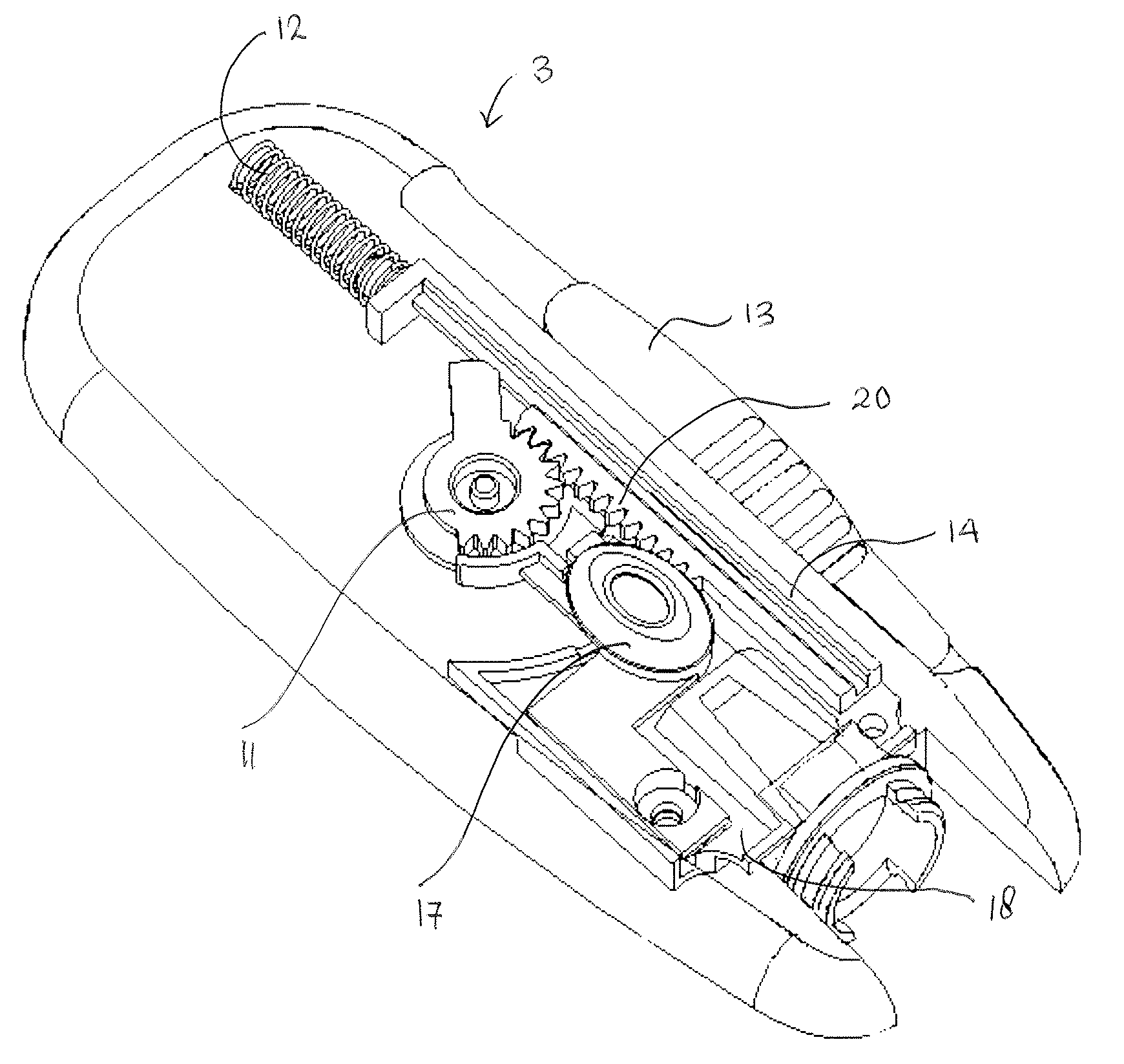
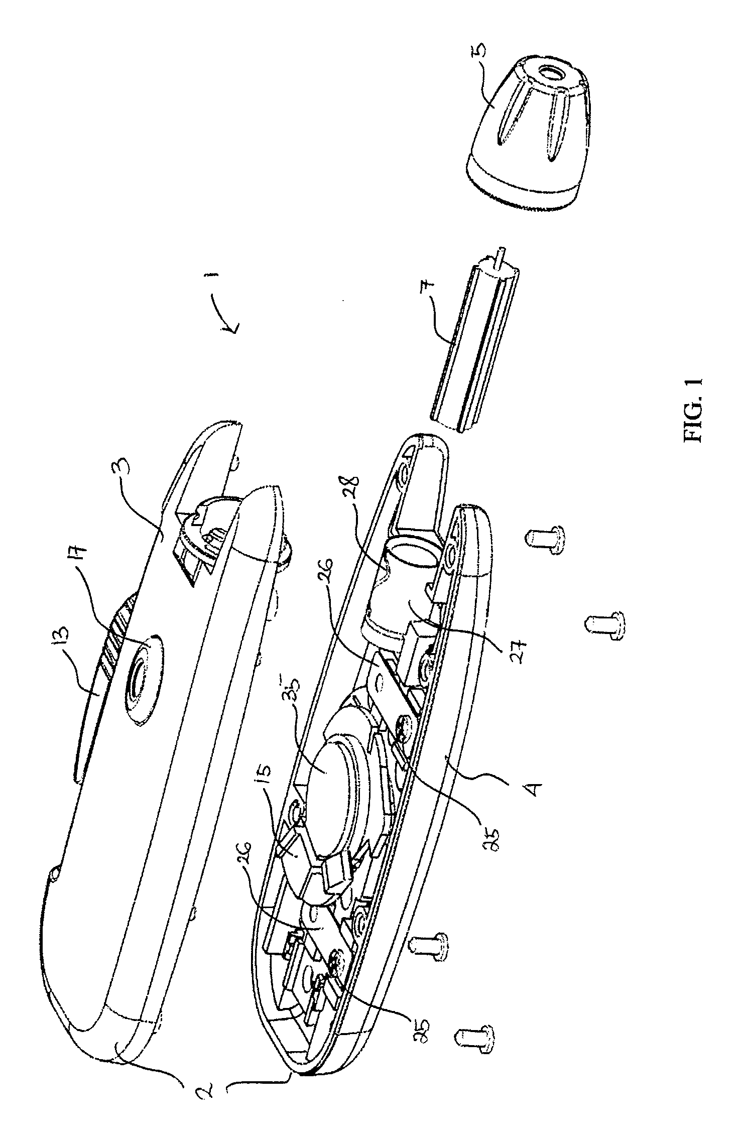
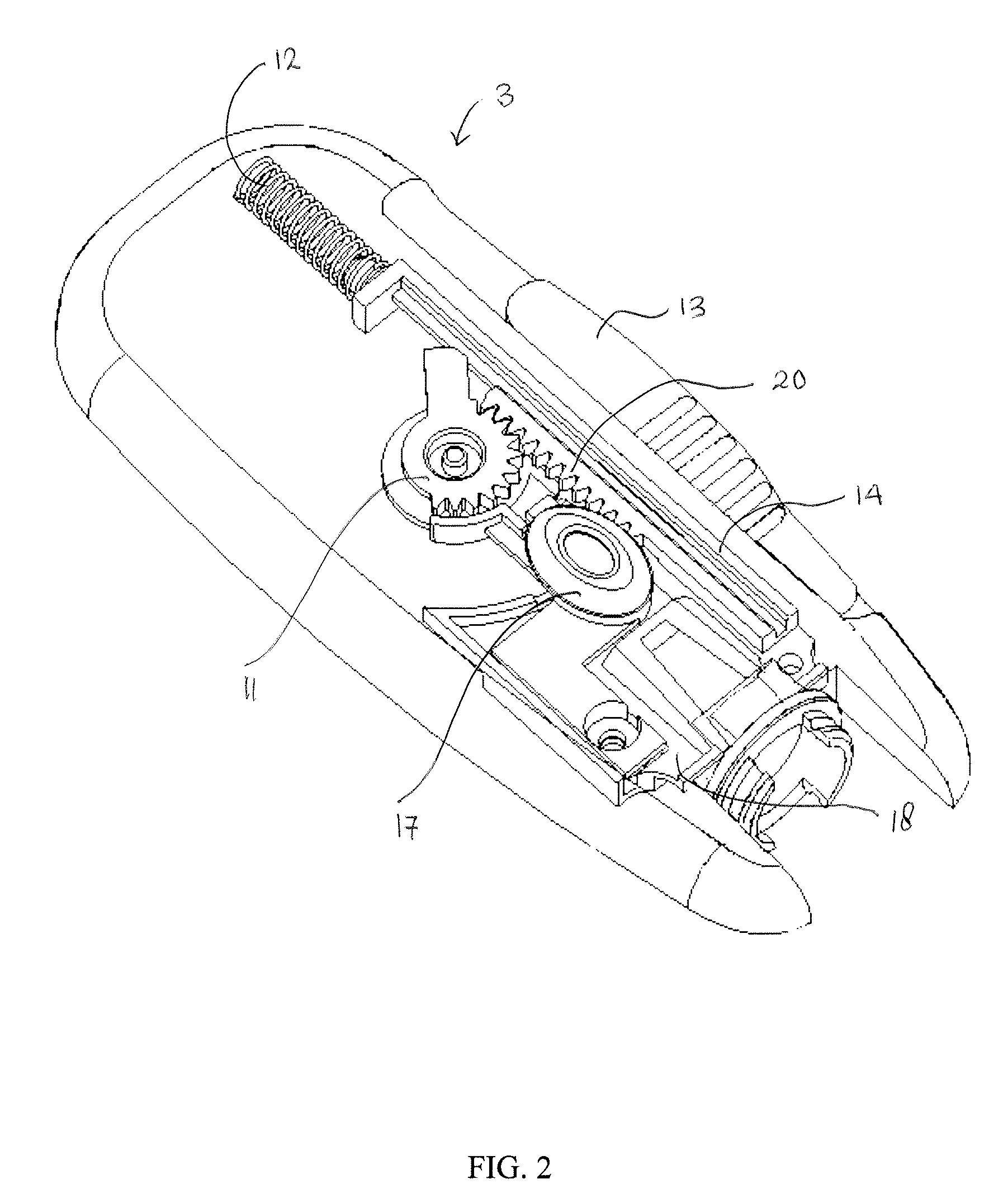
[0032]FIG. 1 shows a perspective view of a lancing device according to one embodiment of the present invention. In this embodiment of the present invention, a housing 2 of the lancet device 1 comprises of top case 3 and bottom case 4. Screws are used to hold the top case 3 and bottom case 4 together. In another embodiment of the present invention, the top case 3 and bottom case 4 are joined together by ultrasonic welding. A cap 5 is disposed at the front end of the housing 2, which has an opening 6 f...


PUM


Abstract

The present invention provides a lancing device designed for minimizing pain to the user, comprising a probe with cam profile responsible for controlling the lancet speed such that the lancet enters the skin relatively fast, decelerates smoothly and gradually to zero velocity at maximum depth of penetration and retracts slowly and controllably. The housing of the lancet comprises of leaf springs and set of guides for minimizing or eliminating pitching or vibration of the lancet during lancing, hence reducing the pain experienced by the user. The lancing device is further equipped with a gear-damper system for minimizing or eliminating noise produced during lancing process.

Description

FIELD OF THE INVENTION[0001]The present invention generally relates to a lancing device, and in particular to a lancing device for minimizing pain to the user while withdrawing sample fluid.BACKGROUND OF THE INVENTION[0002]Lancing device, or also called a lancet device, is typically used in the medical field to lance or break the surface of the skin of one's finger, in order to extract a small blood sample for self diagnostic purposes.[0003]Good diabetes management requires frequent self-monitoring of blood glucose level through self-testing. Lancing device is a critical tool for obtaining blood samples for glucose measurement. Self-testing of blood glucose is important, as it enables people with diabetes to know their blood glucose level at any time, hence allowing them to exercise tighter blood glucose control. This will help to prevent any potentially serious consequences of very high or very low blood glucose level. It is especially crucial for people who take insulin, as self-t...

Claims


Application Information

Patent Timeline
Patent Type & Authority Applications(United States)
IPC IPC(8): A61B17/34
CPCA61B5/15186A61B5/1411A61B5/150022A61B5/150152A61B5/150412A61B5/150503A61B5/15113A61B5/15117A61B5/15128A61B5/1513A61B5/15132A61B5/1519A61B5/15194
Inventor LAI, SIEW KONGYEO, CHOW KIAN
Owner VENTURE CORP LTD
Learn More