Serrated Pipe Cutter and Serrated Blade Therefor

a serrated pipe cutter and cutter technology, applied in the field of cutting tools, can solve the problems of reducing the pressure applied to the article, deformation of the article in the area, and increased force required to initiate the cutting into the article, so as to improve the cutting edge wear, improve the cutting performance, and effectively increase the length of the cutting edg

Inactive Publication Date: 2010-06-17
BLACK & DECKER INC
View PDF100 Cites 4 Cited by
  • Summary
  • Abstract
  • Description
  • Claims
  • Application Information

AI Technical Summary

Benefits of technology

[0020]One advantage of the present invention is that the serrations along the cutting edge improve cutting performance by providing additional cutting points and by effectively increasing the length of the cutting edge in comparison to straight edge blades. Further, the serrations improve cutting edge wear, as the additional cutting points initiate the cut, which effectively reduces the amount of force applied to the sharpened recessed curves that continue the cut.
[0021]Another advantage of the currently preferred embodiments of the present invention is that the substantially concave recess of the jaw supports the pipe, allowing for easier execution of the cut. Another advantage of the currently preferred embodiment of the present invention is that the slot formed within the jaw receives at least a portion of the blade in the second position, thereby ensuring that a clean cut is made through the pipe. Yet another advantage of the currently preferred embodiments of the present invention is that, as the cut is made via a downwardly applied force, and not by a sawing action, the tool may be used in a tight or narrow space. Another advantage of the currently preferred embodiments of the present invention is that the locking mechanism is engageable to ensure that the two handles remain closed when desired, providing easy mobility and safe storage of the pipe cutter.
[0022]Other advantages of the present invention, and / or of the currently preferred embodiments thereof, will become more readily apparent in view of the following detailed description of the currently preferred embodiments and accompanying drawings.

Problems solved by technology

One drawback associated with cutters of this type is that, when placed in initial contact with an article to be cut, the force applied to the cutting tool is spread along the entire edge of the straight blade, thereby reducing the pressure applied on the article; as such, an increased force is required to initiate the cut into the article.
Not only is this increased force burdensome for the user, it presents a further drawback of potentially resulting in deformation of the article in the area surrounding the applied force.
One drawback associated with cutting tools of this variety is that, as the blade passes through the article, its lateral sides remain in constant contact with the interior material of the article.
One drawback associated with cutting tools of this kind is that they do not include a support system for the article, thereby requiring the user to support the article separately in a cumbersome fashion as the cut is made.
Another drawback associated with cutting tools of this nature is that they can only be used in an area that provides sufficient space for the user to effect the lateral-motion cut.

Method used


Image

  • Serrated Pipe Cutter and Serrated Blade Therefor
  • Serrated Pipe Cutter and Serrated Blade Therefor
  • Serrated Pipe Cutter and Serrated Blade Therefor

Examples


Embodiment Construction

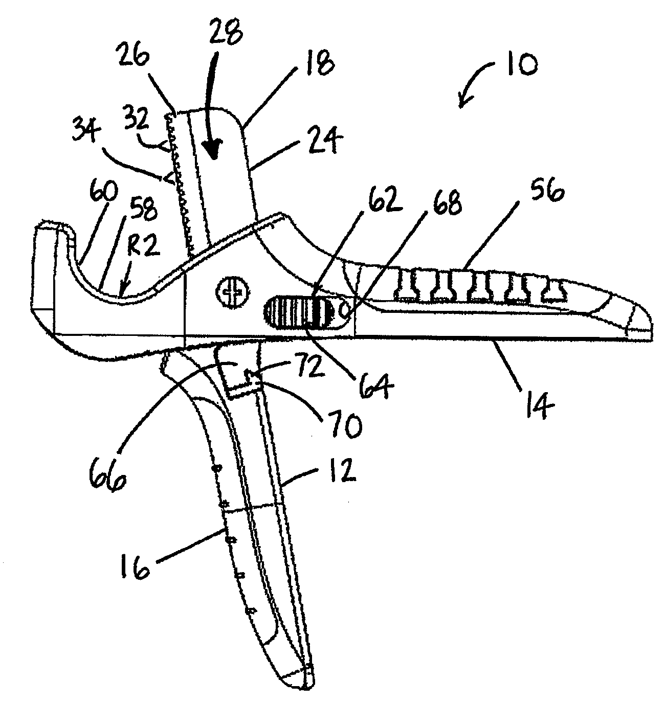
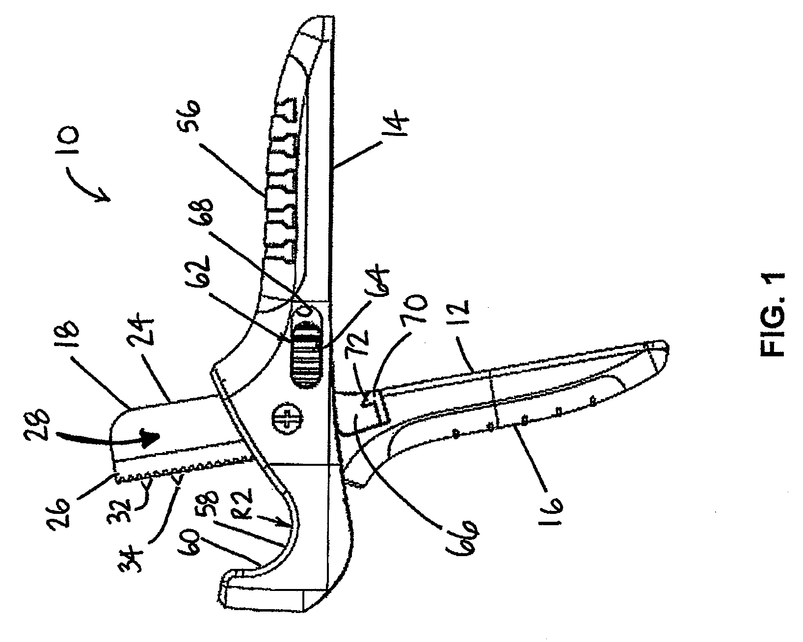
[0033]As illustrated in FIG. 1, a serrated pipe cutter embodying the present invention is indicated generally by the reference numeral 10. The pipe cutter 10 comprises a pair of handles 12 and 14. The handles 12 and 14 are pivotally connected and movable between first and second positions. In the currently preferred embodiment, the cutting tool 10 is a serrated pipe cutter for cutting pipes. The term pipe herein is used to mean any pipe, conduit, duct, hose, tube, or other like hollow or solid article, made in any shape and of any material that is known or becomes known.

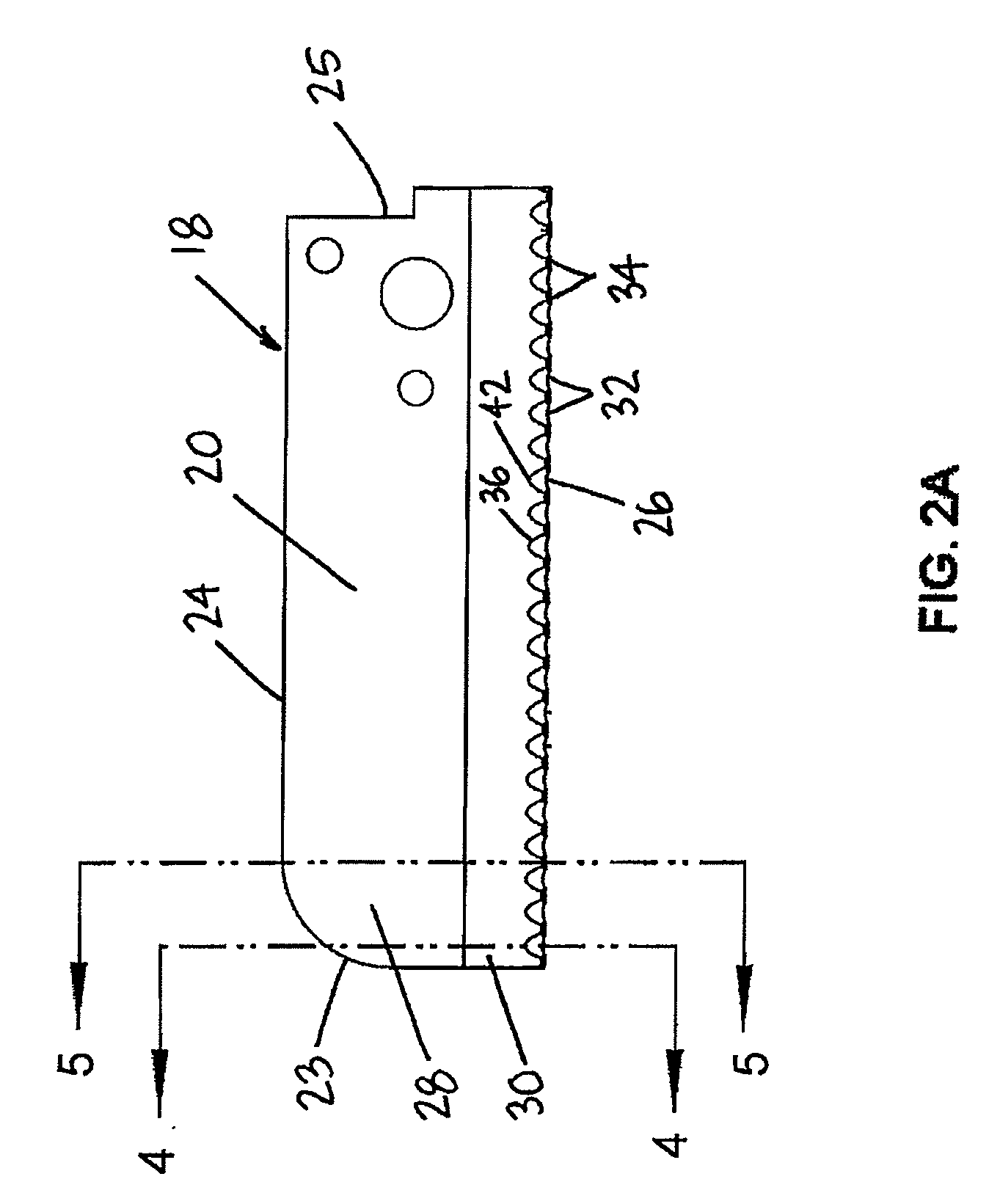
[0034]As shown in FIGS. 1-3, the handle 12 includes a grip 16 at one end and a blade 18 at the opposite end. As illustrated in FIGS. 4A and 5A, the blade 18 includes a first side 20 and a second side 22. As shown in FIGS. 1 and 2, the blade 18 further includes a back edge 24 and a cutting edge 26 located on an opposite side of the blade from the back edge 24. The blade 18 also includes a body 28 extending between the...


PUM

PropertyMeasurementUnit
angleaaaaaaaaaa
angleaaaaaaaaaa
radiusaaaaaaaaaa

Abstract

A serrated pipe cutter comprising handles pivotally coupled together and movable between first and second positions; wherein the first handle includes a grip at one end and a blade at an opposite end; the blade includes an elongated cutting edge which defines a cutting edge surface tapering inwardly, a plurality of serrations extending along the cutting edge, and a plurality of cutting tips extending between adjacent serrations. Each serration defines a cutting edge surface, a substantially concave facet tapering inwardly, and a linear serration cutting edge extending between adjacent cutting tips. Each cutting tip defines a cutting tip surface tapering inwardly and a linear cutting tip edge extending between adjacent serrations, at least a portion of which is offset from at least a portion of the serration cutting edge.

Description

FIELD OF THE INVENTION[0001]The present invention relates to cutting tools and, more particularly, to serrated pipe cutters having a pair of pivoted handles, one of which carries a serrated blade and the other of which supports the article to be cut.BACKGROUND OF THE INVENTION[0002]Cutting tools, particularly handled serrated pipe cutters, have many uses. Conduits and other tubular articles, such as pipes, are often manufactured in bulk and handled cutting tools are often employed to cut the bulk length of manufactured conduit into smaller lengths.[0003]Known types of handled cutting tools include pipe cutters which carry a straight blade. One drawback associated with cutters of this type is that, when placed in initial contact with an article to be cut, the force applied to the cutting tool is spread along the entire edge of the straight blade, thereby reducing the pressure applied on the article; as such, an increased force is required to initiate the cut into the article. Not onl...

Claims


Application Information

Patent Timeline
Patent Type & Authority Applications(United States)
IPC IPC(8): B23D21/10B26B13/08
CPCB26B13/08B26D2001/006B26D3/169B26D1/0006
Inventor HOULE, JOSEPH J.
Owner BLACK & DECKER INC
Why Eureka
Try Eureka