Rotary compressor and refrigeration cycle equipment

a compressor and refrigeration cycle technology, applied in the direction of positive displacement liquid engines, light and heating apparatus, liquid fuel engines, etc., can solve the problems of large increase in crankshaft sliding loss and inability to increase, so as to reduce leakage loss, reduce the height of the cylinder, and improve the performan

Active Publication Date: 2010-06-17
TOSHIBA CARRIER CORP
View PDF8 Cites 12 Cited by
  • Summary
  • Abstract
  • Description
  • Claims
  • Application Information

AI Technical Summary

Benefits of technology

[0012]In other words, the leakage loss is decreased and the compression efficiency is improved, if the ratio of the cylinder inside diameter φDa and eccentricity E [H / (φDa•E)) to the cylinder height H, or the value K, is set small. Particularly, when using a working fluid which is largely different in high and low pressures, the value K needs to be decreased furthermore.
[0017]The present invention has been made in the above circumstances. It is an object of the invention to provide a high performance reliable rotary compressor, which confirms an optimum balance between a value K [H / (φDa•E)] and L / φDb, decreases the height of cylinder, decreases leakage loss and sliding loss, ensures exclusion capacity, and improves compression efficiency, and refrigeration cycle equipment, which uses the rotary compressor, and improves the efficiency of refrigeration cycle.

Problems solved by technology

According to the drawing, it is obvious that when the L / φDb is small, the sliding loss of the crankshaft is largely increased.
However, when the value K is decreased, the cylinder inside diameter φDa is limited by the outside diameter of a sealed case housing a rotary compressor, and cannot not be increased over a certain value.

Method used


Image

  • Rotary compressor and refrigeration cycle equipment
  • Rotary compressor and refrigeration cycle equipment
  • Rotary compressor and refrigeration cycle equipment

Examples


Embodiment Construction

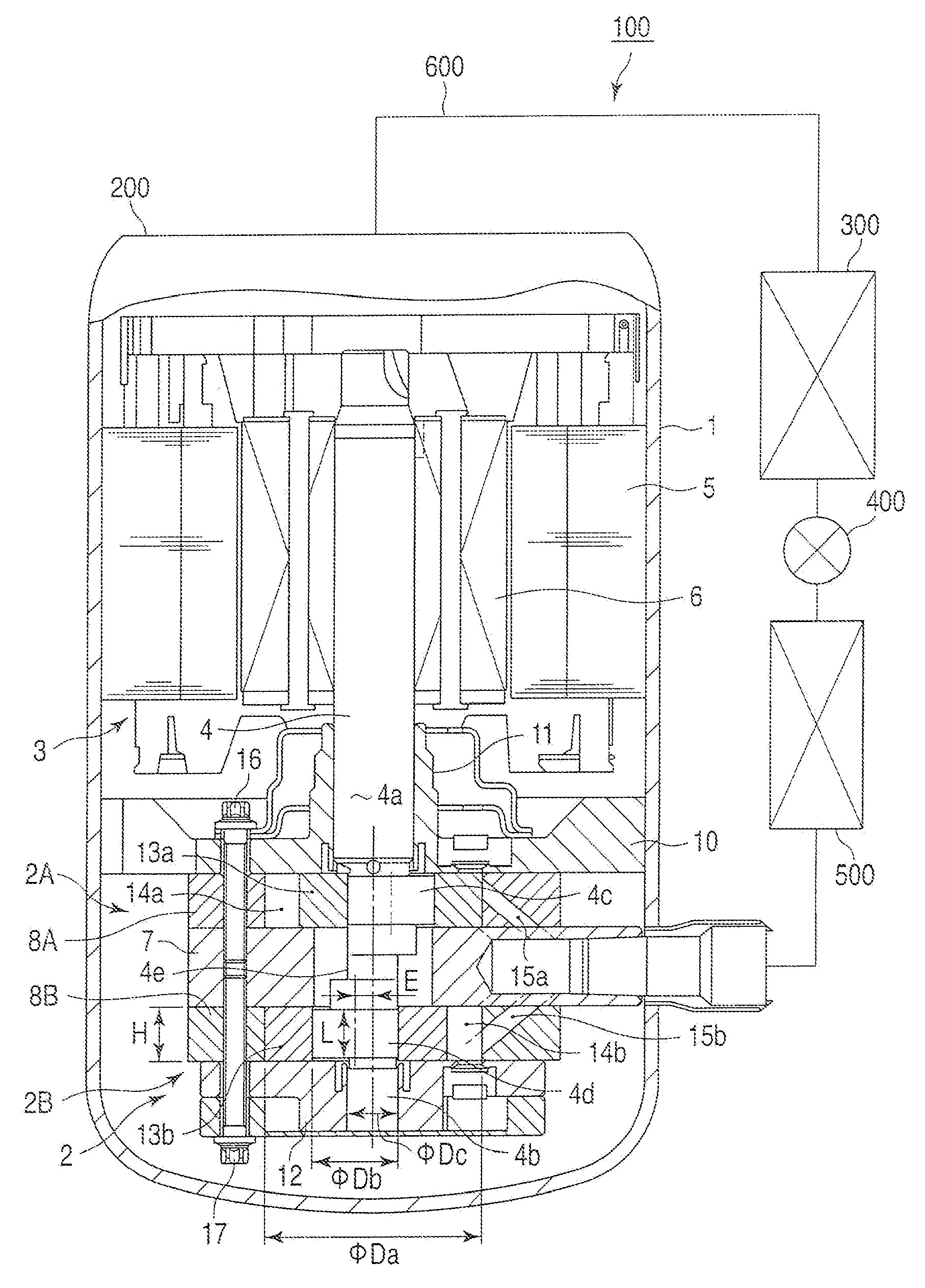
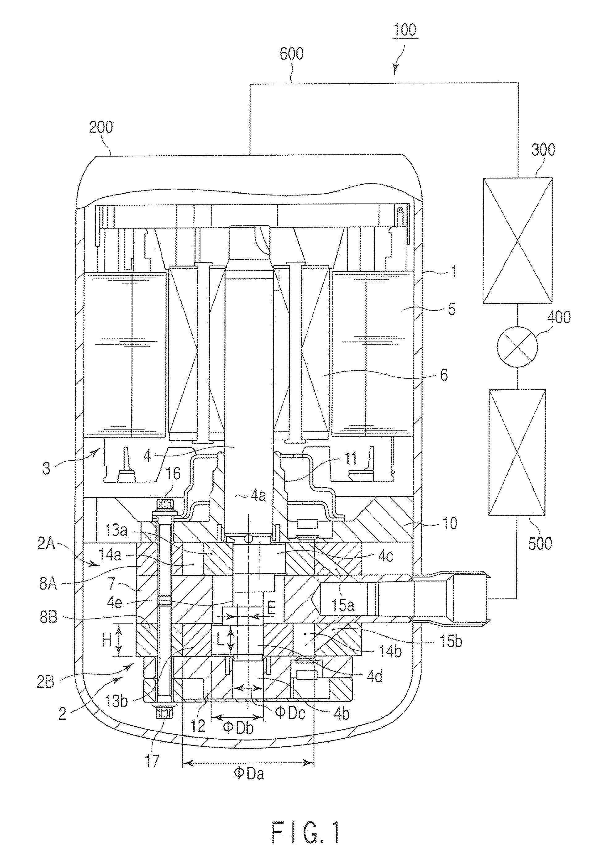
[0024]FIG. 1 shows a cross section structure of a rotary compressor 200, and a block diagram of refrigeration cycle equipment 100 comprising the rotary compressor 100. (To simplify the drawing, the parts, which are explained but not denoted by reference numbers, are not shown, or shown in the drawing but not denoted.)

[0025]First, the configuration of the refrigeration cycle equipment 100 will be explained. The refrigeration cycle equipment 100 comprises a rotary compressor 200, a condenser 300, an expansion device 400, an evaporator 500, and a not-shown gas-liquid separator. These components are sequentially communicated through a refrigerant pipe 600. As described later, refrigerant gas is compressed by the rotary compressor 200, discharged to the refrigerant pipe 600, circulated through the above components, forming a refrigerating cycle, and drawn into the rotary compressor 200.

[0026]Next, the rotary compressor 200 will be described in detail.

[0027]A reference number 1 in FIG. 1 ...


PUM


Abstract

A rotary compressor, which contains a motor unit and compression mechanism in a sealed case, transmits the rotational power of the motor to the compression mechanism through a rotary shaft and crankshafts eccentrically provided in the rotary shaft, and compresses a refrigerant in the compression mechanism, wherein the rotary compressor is configured to have H / (φa•E)=K, and K≦0.065, and the formula 0.35+0.07•K•H≦L / φDb≦0.45+0.07•K•H, assuming that the inside diameter of the cylinder forming the compression mechanism is φDa [mm], the cylinder height is H [mm], the crankshaft eccentricity is E [mm], the crankshaft diameter is φDb [mm], and the sliding lengths of the crankshaft and a roller fitted over the crank are set to L [mm].

Description

CROSS REFERENCE TO RELATED APPLICATIONS[0001]This is a Continuation Application of PCT Application No. PCT / JP2008 / 065460, filed Aug. 28, 2008, which was published under PCT Article 21(2) in Japanese.[0002]This application is based upon and claims the benefit of priority from prior Japanese Patent Application No. 2007-221615, filed Aug. 28, 2007, the entire contents of which are incorporated herein by reference.BACKGROUND OF THE INVENTION[0003]1. Field of the Invention[0004]The present invention relates to a rotary compressor to compress a refrigerant, and refrigeration cycle equipment such as an air conditioner and refrigerator using the rotary compressor.[0005]2. Description of the Related Art[0006]Large capacity has been demanded in a rotary compressor, which contains a motor unit and a compression mechanism in a sealed case, transmits the rotational power of the motor to the compression mechanism through a rotary shaft and crankshafts eccentrically provided in the rotary shaft, a...

Claims


Application Information

Patent Timeline
Patent Type & Authority Applications(United States)
IPC IPC(8): F25B1/04F04C18/00
CPCF04C18/356F04C2250/00F04C23/008
Inventor HIRAYAMA, TAKUYA
Owner TOSHIBA CARRIER CORP
Why Eureka
Try Eureka