Kneading Element of Kneader, Kneader, and Bread Machine

a technology of kneading element and bread machine, which is applied in the directions of mixing/kneading structural elements, baking plants, transportation and packaging, etc., can solve the problems of difficult hand-kneading in these steps, dough and the like cannot be removed, and the effect of effective kneading of ingredients and effective kneading

Inactive Publication Date: 2010-06-17
JAPAN KNEADER
View PDF6 Cites 32 Cited by
  • Summary
  • Abstract
  • Description
  • Claims
  • Application Information

AI Technical Summary

Benefits of technology

[0043]According to the present invention, because the dough material within the pot can be scooped up and rotated on the kneading element and further flipped and tossed toward the inner circumferential surface of the pot, great pressure can be applied directly from the entire area of the inner circumferential surface of the pot to the dough material pressurized by the kneading element, whereby the entire area of the inner circumferential surface of the pot can be effectively used to knead the ingredients effectively.
[0044]Further, according to the present invention, because the dough can be kneaded without cutting it, gluten formed by kneading the dough and having an appropriately balanced combination of glutinosity and elasticity is inseparable. Since there is no friction caused by cutting the dough, no heat is generated locally on the dough, and thereby the dough is not adversely affected.
[0045]Moreover, according to the present invention, due to the action of the space between the erection surface provided in the kneading element and the bottom surface of the pot, even when the dough mass has a large diameter, adhesion of the dough to the kneading element is significantly alleviated. Because the dough is folded by this space, better kneading can be performed

Problems solved by technology

However, it takes considerable effort and is actually difficult to perform hand-kneading in these steps, that is, to perform these steps with hands.
For this reason, the problem is that ingredients and dough enter the space between the kneading element and the bottom surface within the pot and that these dough and the like cannot be removed.
Furthermore, the dough is rolled by centrifugal force generated by the rotation of the disk, and rolling friction, which increases as the hydration of the dough develops.
Therefore, when the rolling friction surpasses the centrifugal force, the dough adheres to the disk and rotates integrally with the disk, and as a result, good kneading cannot be performed.
Hence, another problem is that, when using this kneader, the diameter of the dough mass has to be equal to or less than the radius of the disk of the kneading element.
Moreover, the presence of the projected parts in the inner circumferential surface of the pot makes it difficult to clean the inside of the pot after using the kneader.
However, in the kneading element described in Patent Literature 4, because the side surface extending from the bottom part to the top surface is formed into a bluffy surface throughout the entire circumference of the bottom part, the kneading effect of scooping up a dough material is not very significant.
However, in the kneading element described in Patent Literature 4, because the side surface extending from the bottom part to the top surface is formed into a bluffy surface throughout the entire circumference of the bottom part, this “hand-kneading” effect obtained in the series of flows described above is not very significant.

Method used


Image

  • Kneading Element of Kneader, Kneader, and Bread Machine
  • Kneading Element of Kneader, Kneader, and Bread Machine
  • Kneading Element of Kneader, Kneader, and Bread Machine

Examples


Embodiment Construction

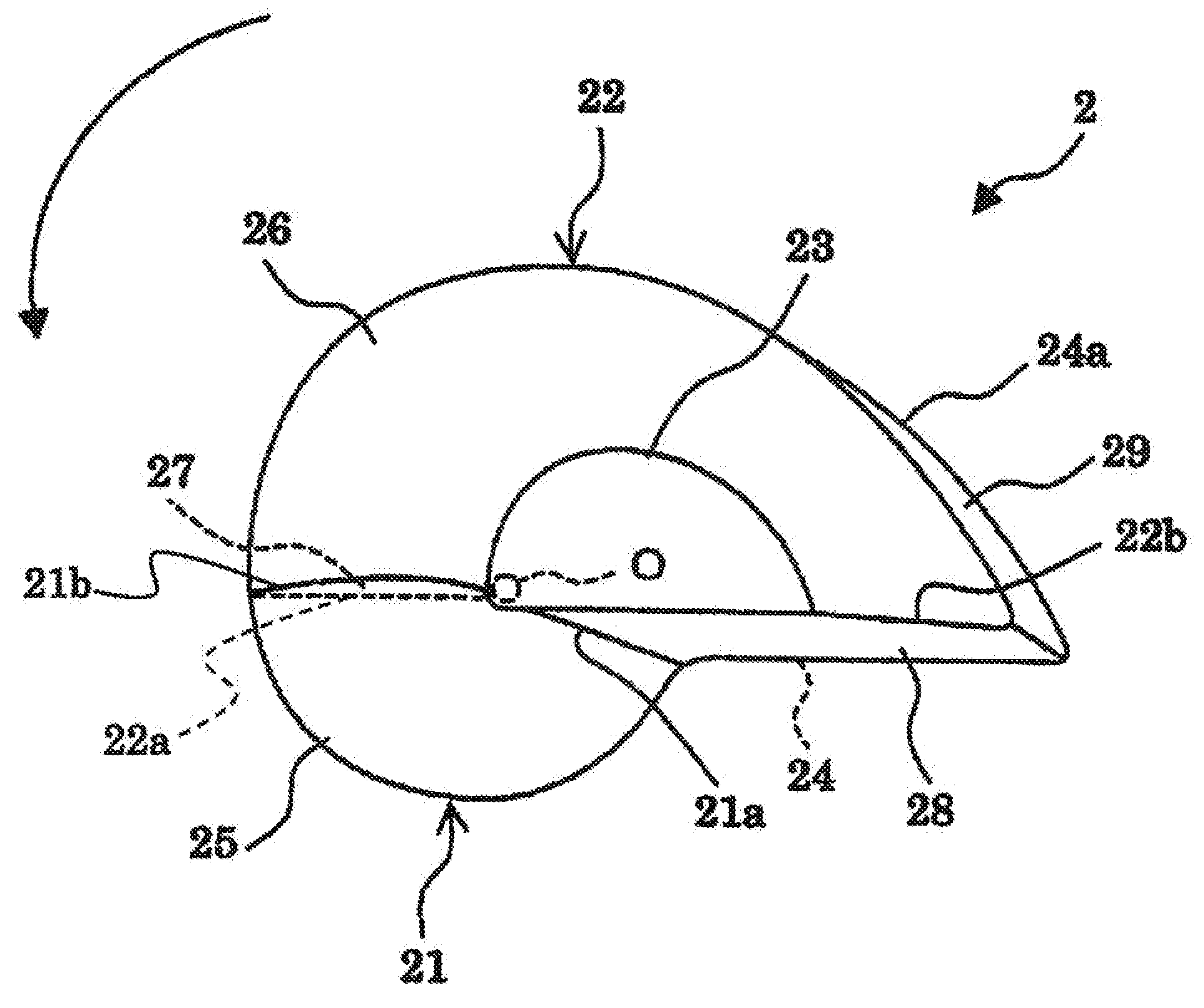
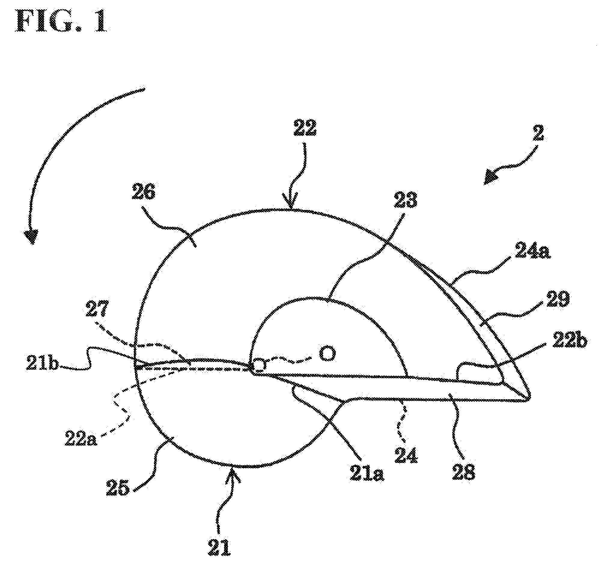
[0100]Embodiments of the kneading element of a kneader and of the kneader according to the present invention will be described hereinafter in detail with reference to the drawings.

[0101]First, the embodiments of the kneading element of a kneader according to the present invention (to be simply referred to as “kneading element” hereinafter) will be described.

[0102]The kneading element, which is disposed rotatably within a pot of a kneader for producing a kneaded product, is rotary driven in a rotating shaft direction orthogonal to a bottom surface of a pot and kneads ingredients within the pot.

[0103]Note the following describes the kneading element as if two blade parts are created individually and bonded with each other to create the kneading element. However, when actually creating the kneading element, the two blade parts may be created integrally by cutting or pressing an aluminum block, or by using other creation method. Further, at the end, a surface of the kneading element may...


PUM

PropertyMeasurementUnit
angleaaaaaaaaaa
inclination angleaaaaaaaaaa
heightaaaaaaaaaa

Abstract

A kneading element is rotary driven around a rotating shaft disposed in a bottom part in a pot to knead ingredients within the pot. The kneading element has a blade part that has a bottom surface circumferential edge that is substantially semi-elliptical, wherein an inclined surface is formed in a side surface of the blade part, an erection surface is formed in a rotation direction back surface of the blade part, and the inclined surface is formed such that ingredients to be kneaded are rotated on the inclined surface. According to this configuration, because dough materials within the pot can be scooped up and rotated on the kneading element and furthermore flipped and tossed toward the inner circumferential surface of the pot, great pressure can be applied directly from the entire area of the inner circumferential surface of the pot to the dough material pressurized by the kneading element, whereby the entire area of the inner circumferential surface of the pot can be effectively used to knead the ingredients effectively.

Description

TECHNICAL FIELD[0001]The present invention relates to a kneading element of a kneader, which is suitable for mixing and kneading and then tamping down a dough material, such as a bread dough, a noodle dough such as wheat and buckwheat noodle, a confectionary dough, or a rice cake. The present invention also relates to a kneader having this kneading element, and a bread machine.BACKGROUND ART[0002]Kneaded products, such as a bread dough, a noodle dough such as wheat and buckwheat noodle, a confectionary dough, and a rice cake, are made by the steps of mixing, kneading and pounding predetermined ingredients into cakes.[0003]In the case of making a bread dough with a direct kneading process, the steps described above contain repeated operations of first mixing ingredients such as flour, water, yeast, sugar, salt and shortening, and thereafter kneading and folding the obtained mixed ingredient. By appropriately and adequately carrying out these steps, hydration, that is, formation and b...

Claims


Application Information

Patent Timeline
Patent Type & Authority Applications(United States)
IPC IPC(8): A21B7/00B01F7/00A21C1/00B01F15/06
CPCA21C1/02B01F7/162B01F7/00275B01F27/1123B01F27/808A21C1/14A47J37/00A47J43/046
Inventor OOCHI, SYUZO
Owner JAPAN KNEADER
Why Eureka
Try Eureka