LED lighting fixture

a technology of led lighting fixtures and led chips, which is applied in the direction of lighting and heating apparatus, semiconductor devices for light sources, lighting support devices, etc., can solve the problems of difficult to increase the light output power, sapphire substrates provide high thermal resistance, and single white leds are not enough to produce the desired light output power, etc., to inhibit the increase in the temperature of led chips and suppress the effect of transfer

Inactive Publication Date: 2010-06-17
MATSUSHITA ELECTRIC WORKS LTD
View PDF17 Cites 38 Cited by
  • Summary
  • Abstract
  • Description
  • Claims
  • Application Information

AI Technical Summary

Benefits of technology

[0024]In this case, the air layer can function as a thermal insulation layer to suppress transfer of h...

Problems solved by technology

For applications such as general lights that require a relatively large light output power, a single white LED is not enough to produce a desired light output power.
In such a conventional technique, a portion from the light-emitting part of each LED chip 10′ or 10″ to the fixture body has a high level of thermal resistance, and therefore the power input to each LED chip 10′ or 10″ has to be ...

Method used


Image

  • LED lighting fixture
  • LED lighting fixture
  • LED lighting fixture

Examples


embodiment 1

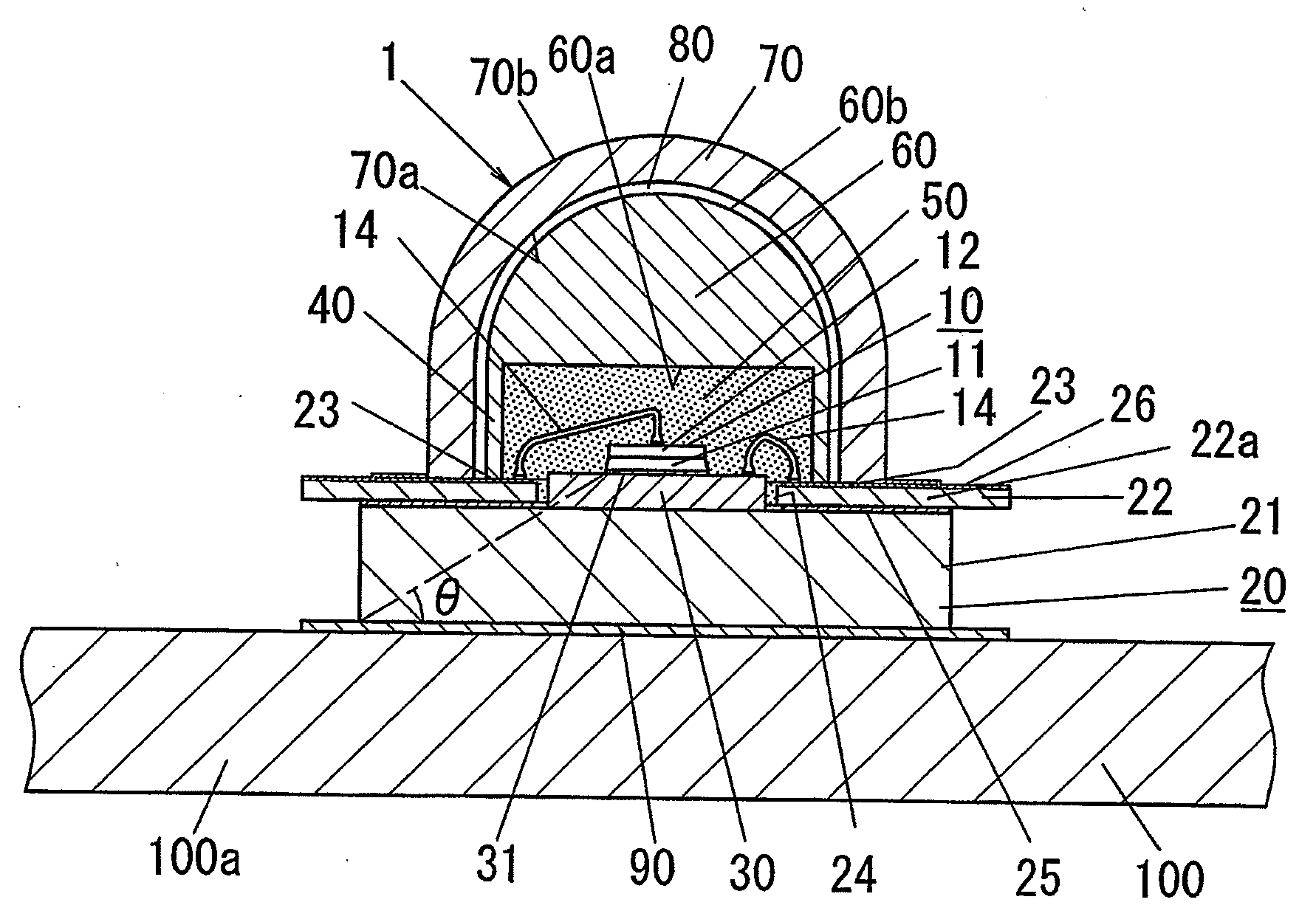
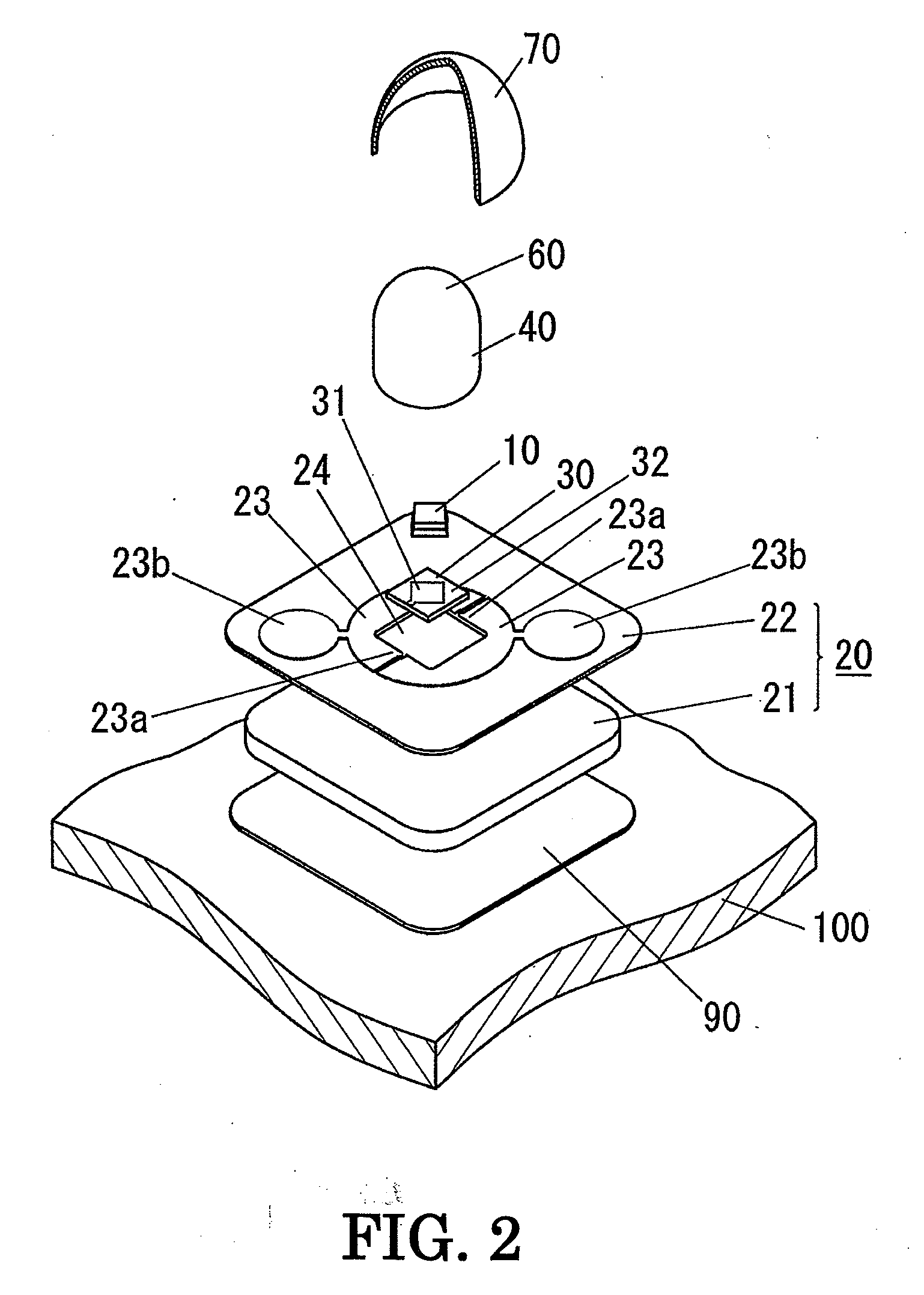
[0045]An LED lighting fixture according to the present embodiment is described in detail below with reference to FIGS. 1 to 9 attached hereto.

[0046]The LED lighting fixture of the present embodiment is typically for use as a spotlight and includes, as shown in FIG. 7, a mount 110, a rotary base 120 fixed on the mount 110, an arm 122 with its one end coupled to the rotary base 120 with a screw shaft 121, and a fixture body 100 of a metal (for example, a highly thermal conductive metal such as Al and Cu) coupled to the arm 122 with a coupling screw 123.

[0047]The fixture body 100 is in the form of a bottomed shallow cylinder having an opening on one end. A plurality of light-emitting devices 1 (eight devices in the present embodiment) and a circular plate-shaped circuit board 200 (see FIG. 8) are housed in the fixture body 100, and the one end is sealed with a front cover 130. Each light-emitting device 1 includes an LED chip 10 and a mount board 20 having patterned conductors 23, 23 f...

embodiment 2

[0094]An LED lighting fixture according to the present embodiment is described below with reference to FIGS. 10 to 17 attached hereto.

[0095]The basic configuration of the LED lighting fixture of the present embodiment is substantially the same as that of Embodiment 1, except that there are differences in the structures of the light-emitting device 1 and the circuit board 200 between them. It should be noted that the same element as in Embodiment 1 is represented by the same reference mark, and a description thereof is omitted.

[0096]In the present embodiment, the light-emitting device 1 does not include the frame 40 described in Embodiment 1; the optical component 60 for controlling the distribution of light emitted from the LED chip 10 is in the form of a dome and placed on one side of the mount board 20 so as to house the LED chip 10 together with the mount board 20; the space surrounded by the optical component 60 and the mount board 20 is filled with the encapsulation part 50 in ...


PUM


Abstract

A light-emitting device held on a fixture body includes an LED chip, a heat transfer plate made of a thermally conductive material on which the LED chip is mounted, a wiring board having, on one side, patterned conductors, for supplying an electric power to the LED chip and formed with an aperture (exposure part) through which a LED chip mount surface of the heat transfer plate is exposed, an encapsulation part in which the LED chip is encapsulated on the one side of the wiring board, and a dome-shaped color-changing member made of a fluorescent material and an optically transparent material and placed on the one side of the wiring board. The light-emitting device is bonded to the fixture body with an insulating layer interposed therebetween, and the insulating layer has electrical insulating properties and is interposed between the heat transfer plate and the fixture body to thermally couple the same.

Description

TECHNICAL FIELD[0001]The present invention relates to an LED lighting fixture including an LED chip (light-emitting diode chip)-containing light-emitting device as a light source.BACKGROUND ART[0002]Research and development have been widely conducted on light-emitting devices that use LED chips in combination with fluorescent materials (such as fluorescent pigments and dyes). In such devices, the fluorescent materials serve as wavelength conversion materials capable of being excited by light emitted from the LED chips and emitting light of a color different from that of the LED chips so that the devices can emit light of a color different from that emitted from the LED chips. Concerning this type of light-emitting devices, there have been commercially manufactured, for example, white light-emitting devices (generally called white LEDs) that use fluorescent materials in combination with blue or violet light-emitting LED chips to produce white light (white light emission spectrum).[00...

Claims


Application Information

Patent Timeline
IPC IPC(8): H01L33/00H01L33/48H01L33/50H01L33/58H01L33/64
CPCF21K9/00F21V21/30H01L33/486H01L33/505H01L2924/19107H01L33/58H01L33/641H01L2224/73265H01L33/507F21Y2115/10
Inventor KAMADA, KAZUONISHIOKA, YASUSHIURANO, YOUJI
Owner MATSUSHITA ELECTRIC WORKS LTD
Why Eureka
Try Eureka