Blind rivet assembly

a technology of blind rivets and rivet rods, which is applied in the direction of threaded fasteners, fastening means, dowels, etc., can solve the problems of inability to readily increase, and prior fasteners of this type have typically been limited in the width range of workpieces, and achieve high shear strength

Inactive Publication Date: 2010-06-17
SARIV
View PDF6 Cites 4 Cited by
  • Summary
  • Abstract
  • Description
  • Claims
  • Application Information

AI Technical Summary

Benefits of technology

[0004]In the present invention, the above-described problem is solved by using a third component, which allows the stem to plug the workp

Problems solved by technology

The magnitude of the shear load is primarily determined in this type of rivet by the mechanical strength of the stem, while the shear strength which can be attributed to the shell is normally less significant, and cannot be readily increased, since the shell must retain high ductility in order to be deformed dur

Method used


Image

  • Blind rivet assembly
  • Blind rivet assembly
  • Blind rivet assembly

Examples


Embodiment Construction

[0017]The following description of the blind rivet is exemplary in nature and in no way is intended to limit the invention or its applications.

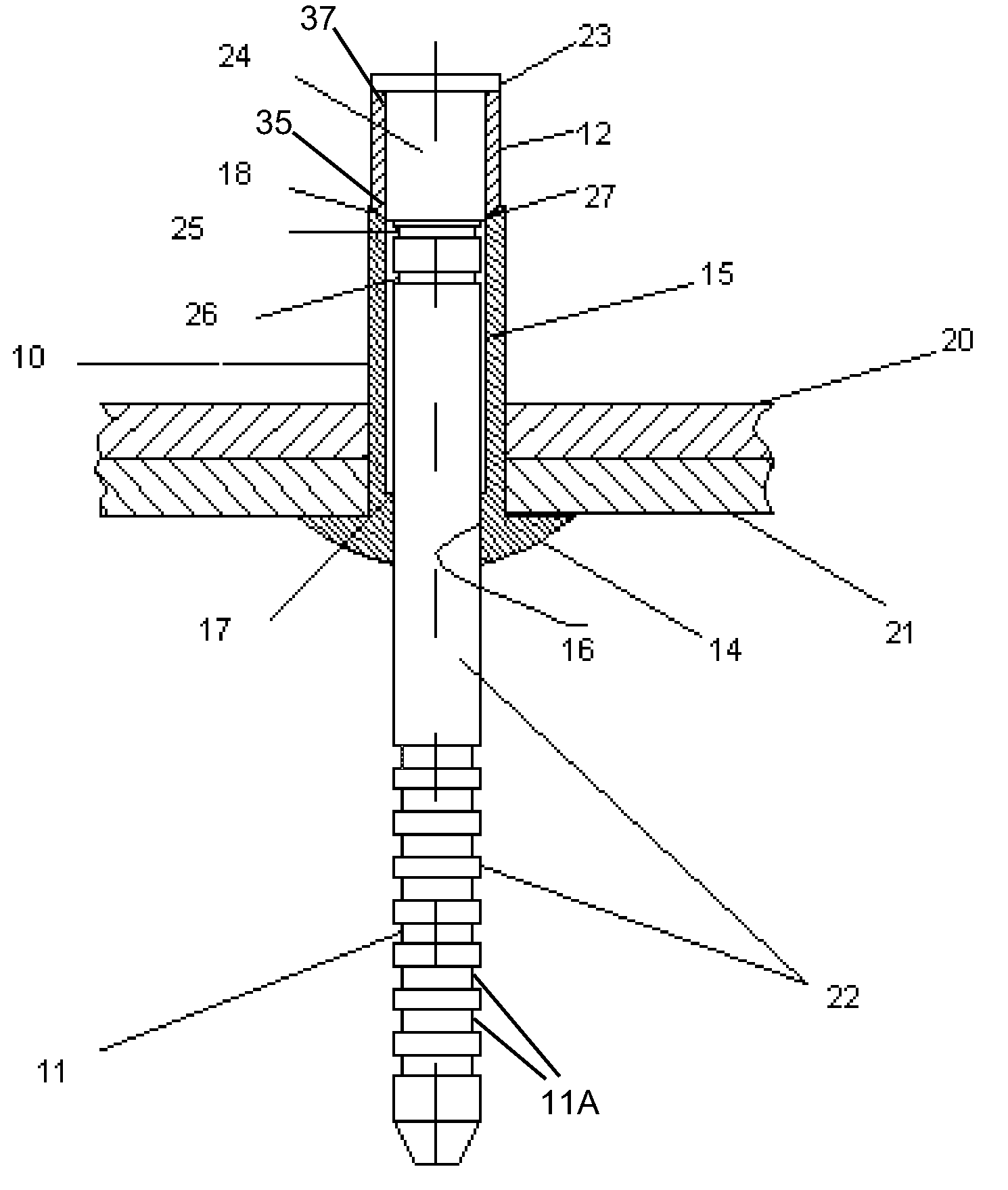
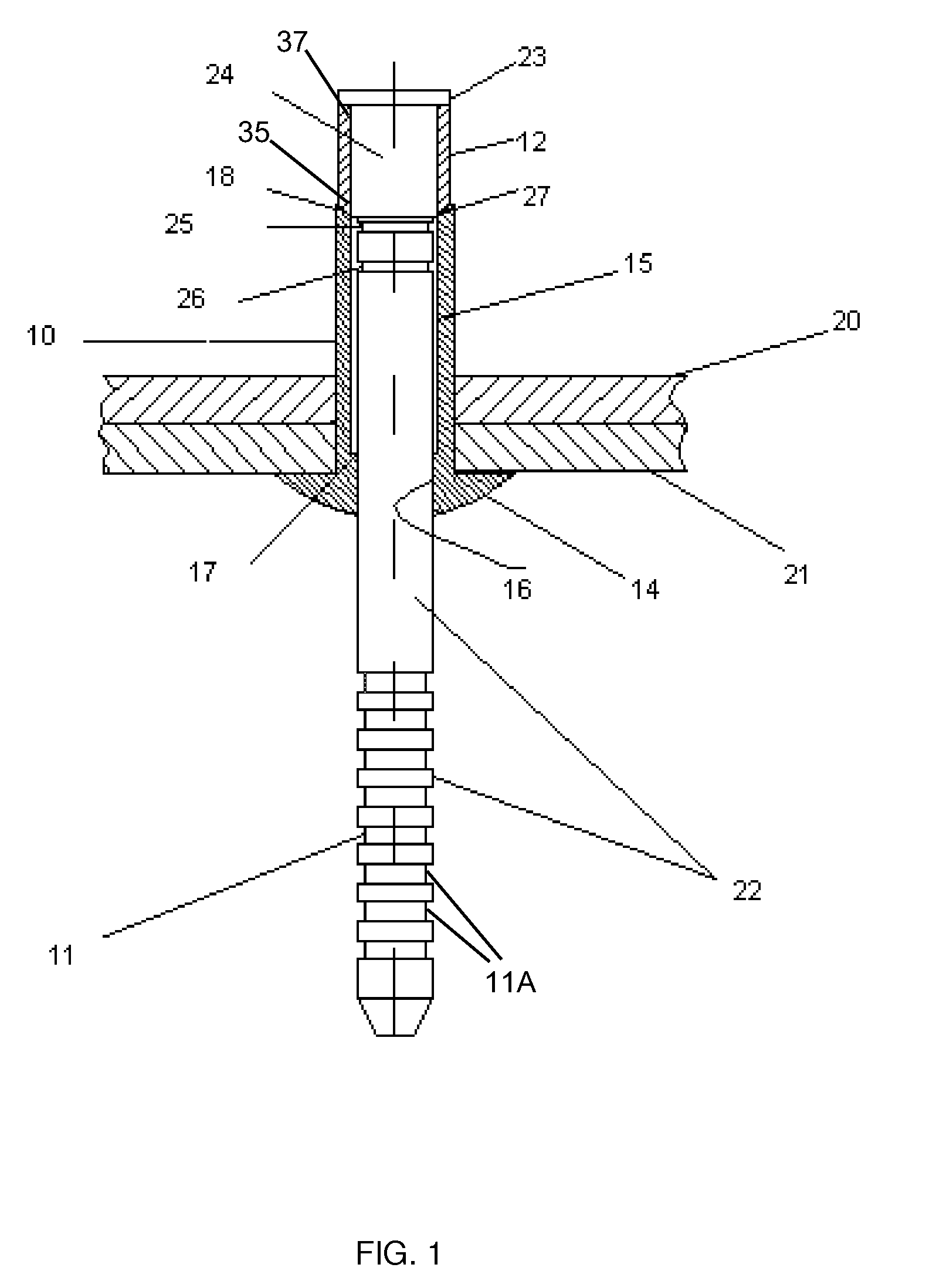
[0018]Referring to FIG. 1, a blind rivet is shown and includes a tubular shell 10, a stem 11 and a placement ring 12 in assembled condition, prior to installation. The rivet is shown placed in workpieces 20 and 21, which are to be fastened together.

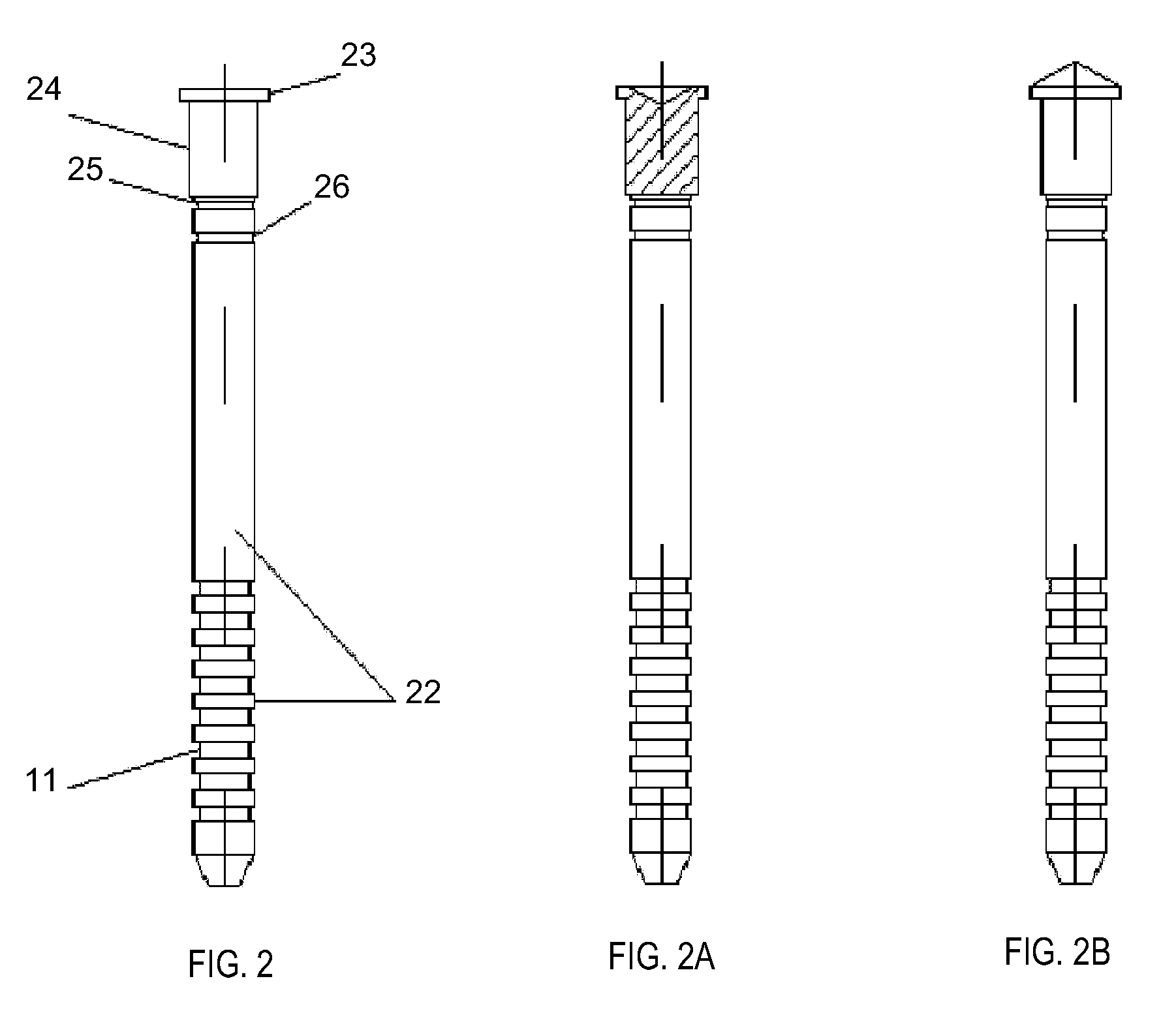
[0019]Referring to FIG. 1 and FIG. 2, the stem 11 has an elongated shank 22 partly grooved, which terminates in an enlarged stem head 23. Under the head is a portion 24 of the shank upon which the placement ring is assembled. A lock-groove 25 and break-groove 26 are located at pre-determined locations. The lock-groove has a diameter designed to allow material from the shell 10 to flow inside the groove during installation, and the break-groove 26 is the weakest section of the stem and will shear at the conclusion of the installation. FIGS. 2A and 2B show other configurations for the stem, namely di...


PUM


Abstract

A blind rivet assembly for securing workpieces having aligned bores with the workpieces having an open surface at an open side and a blind surface at a blind side, the blind rivet assembly including a tubular shell having an enlarged shell head adapted to be in engagement with the open surface of the workpieces, a stem having an elongated shank with a stem head at the far end of the shank and having gripping means at the opposite end adapted to be gripped by an installation tool for application of an axial pulling force, and a placement ring having an near end and a far end, and having a pre-installation orientation and a post-installation orientation, wherein in the pre-installation orientation the placement ring is disposed around a ring receiving portion of the elongated shank, and the post-installation orientation is created by axially pulling the stem towards the open side of the workpieces with an axial pulling force that forces the placement ring into a through bore which causes the shell to deform outwards and form a blind head, and wherein upon continued axial pulling of the stem, the stem progressively moves into the shell until the stem encounters a stop shoulder, whereupon material of the stop shoulder is moved into a locking portion to arrest further movement of the stem, and whereupon increased axial force on the stem shears a portion of the stem on the open side at a shearable break-groove.

Description

FIELD OF THE INVENTION[0001]The present invention relates generally to blind rivet assemblies, and particularly to a blind rivet which will operate in workpieces to be fastened together and will become radially expanded in order to provide hole fill and an interference fit with the surfaces of the openings of the workpieces upon final installation, and clamp the workpieces together.BACKGROUND OF THE INVENTION[0002]In securing workpieces together with a blind fastener, it is desirable to be able to maintain a high final clamp load on the workpieces. At the same time, it is desirable that the installed fastener has the capability of withstanding high shear loads. The magnitude of the clamp load is established by the relative axial force applied between the stem and shell when the blind head is formed and then engages the back surface of the workpiece. The magnitude of the shear load is primarily determined in this type of rivet by the mechanical strength of the stem, while the shear s...

Claims


Application Information

Patent Timeline
IPC IPC(8): F16B13/04
CPCF16B19/1036
Inventor DAVID, SHALOMCHESTERMAN, DANNY
Owner SARIV
Why Eureka
Try Eureka