Swashplateless rotorcraft with fault tolerant linear electric actuator

Active Publication Date: 2010-06-17
KAREM AIRCRAFT INC
View PDF16 Cites 32 Cited by
  • Summary
  • Abstract
  • Description
  • Claims
  • Application Information

AI Technical Summary

Benefits of technology

[0017]It is contemplated that a preferred rotorcraft having an electric blade pitch actuator might also be equipped with a controller that c

Problems solved by technology

When a pitch link passes over this high point, the pitch of the blade is raised, which leads to increase in lift in the vicinity of the high portion of the swashplate.
While swashplates offer a means of controlling a rotorcraft, they are large, heavy, complex, and prone to failure.
The bearings necessary to transfer motion from non-rotating control linkages to rotating pitchlinks need lubrication and may fail.
The mechanical or hydraulic systems associated with such a system are almost invariably complicated, and burden the rotorcraft with additional weight.
Mechanical and hydraulic systems also have higher failure rates and maintenance requirements than all-electric systems.
Because the system of Arnold requires both a conventional swashplate and a slipring, it ha

Method used


Image

  • Swashplateless rotorcraft with fault tolerant linear electric actuator
  • Swashplateless rotorcraft with fault tolerant linear electric actuator
  • Swashplateless rotorcraft with fault tolerant linear electric actuator

Examples


Embodiment Construction

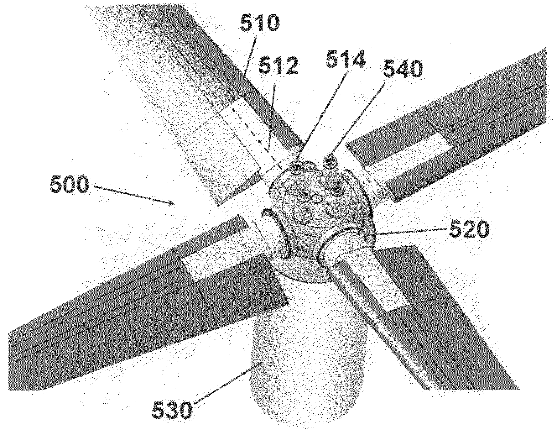
[0033]This specification reveals several inventive apparatus, systems, and methods for providing all-electric fault-tolerant rotor blade control. An especially preferred embodiment is an electric fault-tolerant linear output actuator for a hingeless, swashplateless rotor rotorcraft. As used herein, a “hingeless rotor” is a rotor without discrete mechanical hinges for blade articulation in the flap or lag direction. Hingeless rotor systems have very different behaviors than articulated rotor systems, including higher pitch bearing friction loads, and have different actuation force and size requirements.

[0034]FIG. 5 shows an overview of a preferred hingeless, swashplateless rotor system. The rotor 500 comprises blades 510 coupled to a rotating hub 520 by means of a blade shank 514 which permits pitching of the blade 510 relative the hub 520 about a pitch axis 512. The hub 520 turns relative to non-rotating structure 530 of a rotorcraft. Electric linear actuators 540 are coupled to the...


PUM


Abstract

An electric linear actuator is disposed to pitch a blade of a hingeless, swashplateless rotor in rotary motion. This actuator can be equipped with an electric motor advantageously made fault tolerant by winding the motor for at least 4, 5, 6, 8, or even 12 phases. Rotational motion of the electric motor is preferably converted to a translatory linear actuator output motion using a planetary roller screw coupling the rotation of the motor with pitch of the blade. The output link of the actuator can be advantageously coupled to the planetary roller screw using an internal spherical joint providing an isolated load path through the actuator. It is contemplated that a preferred rotorcraft having an electric blade pitch actuator might also be equipped with a controller that could provide the vehicle with individual blade control, in which the pitch of any rotor blade can be controlled independently of the others.

Description

[0001]This application claims priority to U.S. Provisional Application Ser. No. 61 / 122,219 filed Dec. 12, 2008, which is incorporated by reference herein in its entirety.FIELD OF THE INVENTION[0002]The field of the invention is rotorcraft.BACKGROUND[0003]Current rotorcraft typically achieve controlled flight through the use of a swashplate as shown in FIG. 1. A pilot moves controls 110 which are coupled physically, hydraulically, or electrically to control linkages 120 that do not rotate with the rotor 130. The control linkages 120 can move a swashplate 160 up and down 162 in a collective move or tilt 164 the swashplate 160 in a cyclic 164 mode. The swashplate 160 transfers the motions of the non-rotating control linkages 120 to rotating pitch links 170. The pitch links 170 are coupled to blades 180 such that the blade is caused to rotate about its pitch axis 182. Collective control of blade pitch varies the thrust produced by the rotor, while cyclic control of blade pitch is used t...

Claims


Application Information

Patent Timeline
IPC IPC(8): B64C27/68B64C11/44
CPCB64C27/68B64C2027/7216Y02T50/34F16H2025/2037F16H25/24Y02T50/30
Inventor WAIDE, WILLIAM MARTINKAREM, ABEPATT, DAN
Owner KAREM AIRCRAFT INC
Why Eureka
Try Eureka