Lawn Mower and Droplet Wiping Roller Unit
a technology of lawn mower and droplet, which is applied in the field of lawn mower, can solve the problems of insufficient lawn mower, and inability to achieve high-efficiency lawnmowing
- Summary
- Abstract
- Description
- Claims
- Application Information
AI Technical Summary
Benefits of technology
Problems solved by technology
Method used
Image
Examples
example 1
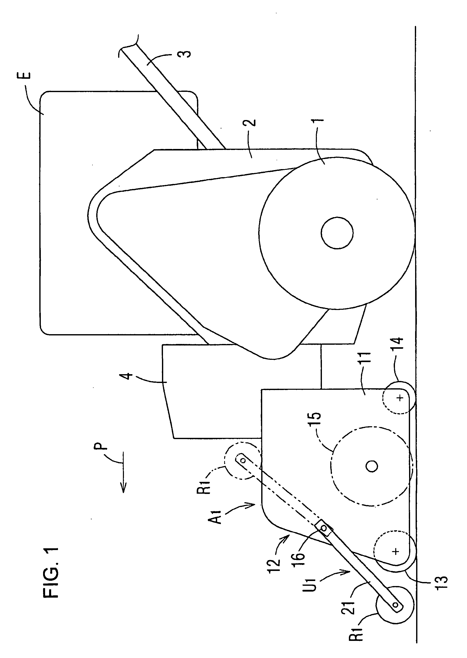
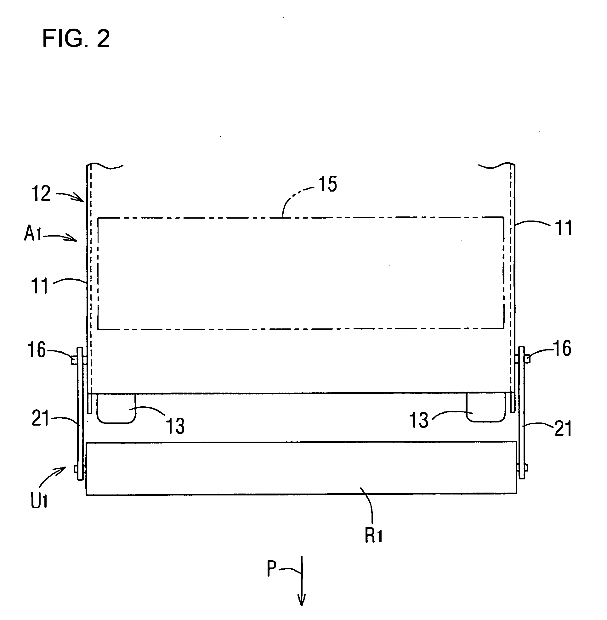
[0034]FIG. 1 is a side view of a walk-along lawn mower having a droplet wiping roller unit U1 mounted to a front portion of a lawn mowing unit A1; FIG. 2 is a plan view showing a portion of the same droplet wiping roller unit U1; and FIG. 3 is a drawing showing operation to allow droplets W on a lawn G to be transferred and adhered to a droplet wiping roller R1. In FIG. 1 and FIG. 2, the lawn mowing unit A1 is mounted to a front portion of a machine body 2 provided with a drive wheel 1. The lawn mowing unit A1 includes a housing 12 having side panels 11, a front roller 13 and a rear roller 14 mounted to front and rear ends of the housing 12 and a reel cutter 15 to be supported by the side panels 11 and rotated by a power of an engine E mounted to the machine body 2, and travels integrally with the machine body 2. In FIG. 1, reference numeral 3 designates a handle of the lawn mower, and reference numeral 4 designates a connector for connecting the machine body 2 and the lawn mowing u...
example 2
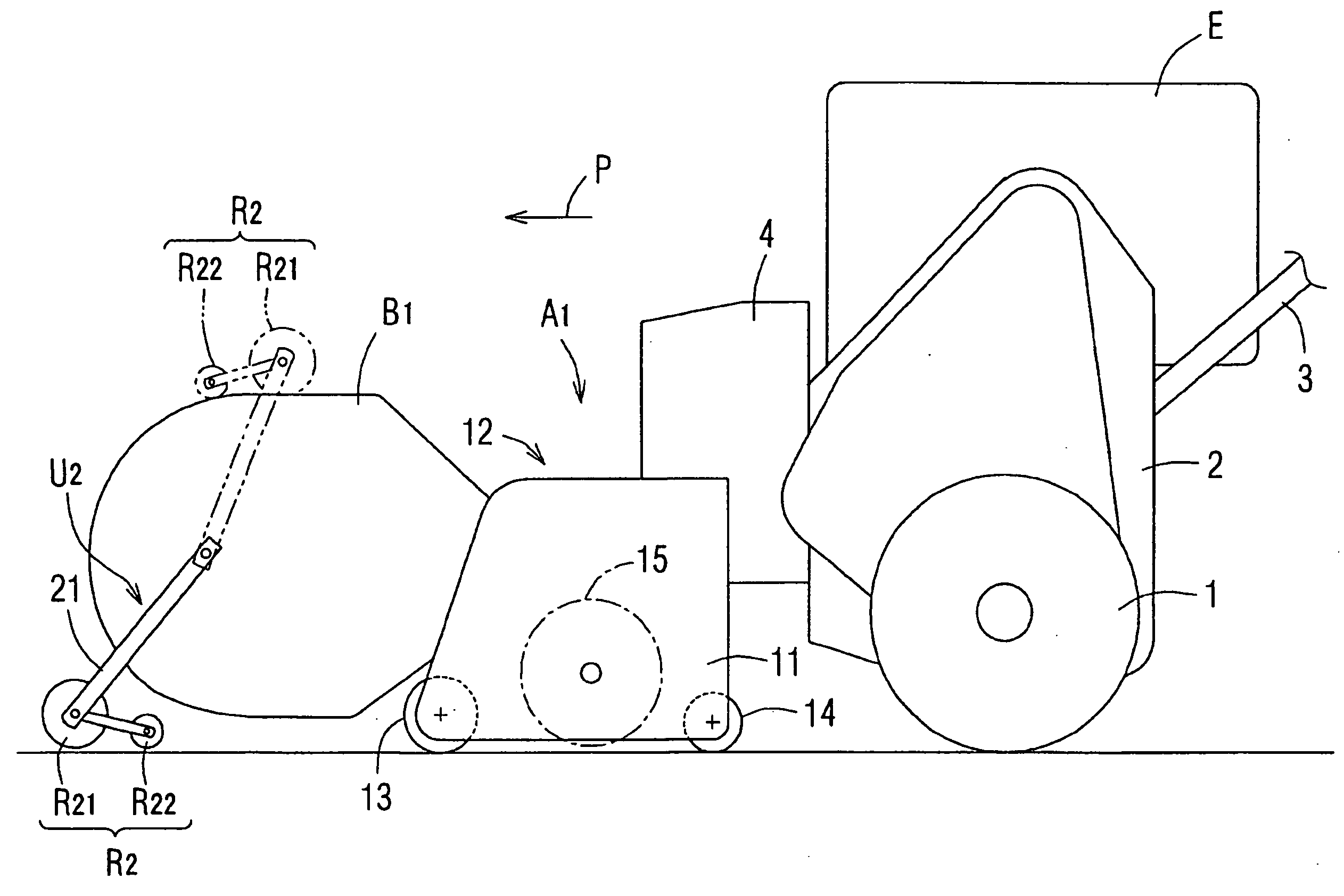
[0038]FIG. 4 is a partial side view of a lawn mower having a droplet wiping roller unit U2 mounted to a front portion of a grass collecting box B1, which is mounted to a front portion of the lawn mowing unit A1. There may be a case in which the grass collecting box B1 for collecting the clippings is mounted on the front portion of the lawn mowing unit A1. In this case, the droplet wiping roller unit U2 is disposed on the front portion of the grass collecting box B1. A droplet wiping roller R2 which constitutes the droplet wiping roller unit U2 in Example 2 includes a large-diameter roller R21 arranged on the front side and a small-diameter roller R22 arranged on the rear side. In Example 2, since the droplet wiping roller R2 is composed of the two rollers R21, R22 having the different outer diameters, the droplets W of the lawn G which are not adhered to the large-diameter roller R21 on the front side have another opportunity to be adhered to the small-diameter roller R22 on the rea...
example 3
[0039]FIG. 5 is a schematic side view of a lawn mower having a droplet wiping roller unit U3 mounted to a front portion of a grass collecting box B2 mounted to a front of a lawn mowing unit A2; FIG. 6 is a partial perspective view of the droplet wiping roller unit U3, and FIG. 7 is a plan view of the droplet wiping roller unit U3 partly broken. The lawn mowing unit A2 includes a reel cutter 32 disposed between the drive wheel 1 and a front roller 31, and a thatching roller 33 that scoops parts of the lawn grasses getting under the lawn for facilitating mowing by the reel cutter 32 on the rear side disposed in front of the reel cutter 32. The droplet wiping roller unit U3 includes a droplet wiping roller R3 including a large-diameter roller R31 formed into a cylindrical shape with resin and a small-diameter roller R32 formed into the same shape with the same material, an arm 34 for connecting the large-diameter roller R31 to both side panel portions 36 of the grass collecting box B2,...
PUM
 Abstract
Description
Claims
Application Information
 - R&D
- Intellectual Property
- Life Sciences
- Materials
- Tech Scout
- Unparalleled Data Quality
- Higher Quality Content
- 60% Fewer Hallucinations
Browse by: Latest US Patents, China's latest patents, Technical Efficacy Thesaurus, Application Domain, Technology Topic, Popular Technical Reports.
© 2025 PatSnap. All rights reserved.Legal|Privacy policy|Modern Slavery Act Transparency Statement|Sitemap|About US| Contact US: help@patsnap.com


