Matrix structure oscillator

Active Publication Date: 2010-06-24
STMICROELECTRONICS INT NV
View PDF3 Cites 22 Cited by
  • Summary
  • Abstract
  • Description
  • Claims
  • Application Information

AI Technical Summary

Benefits of technology

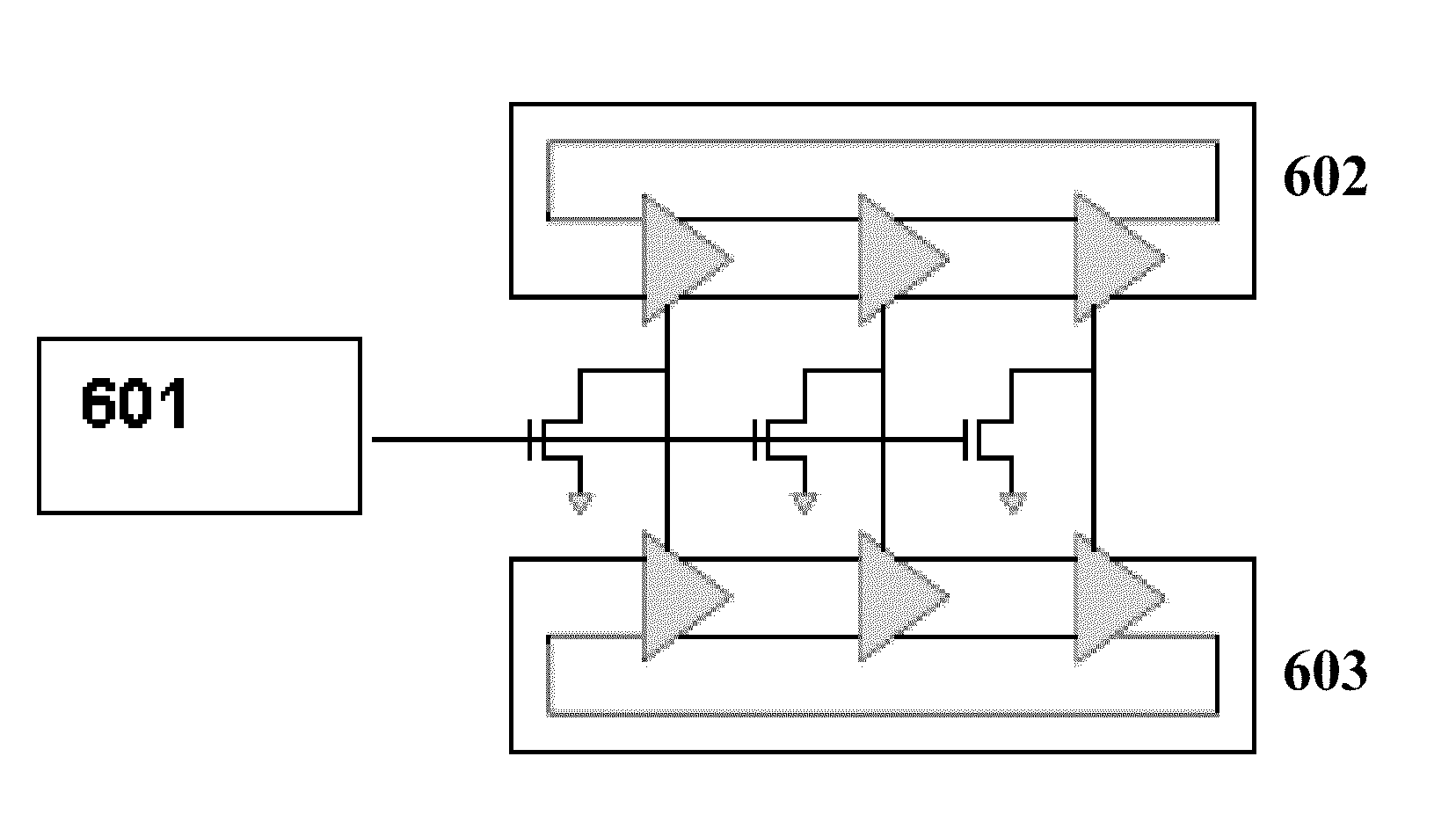
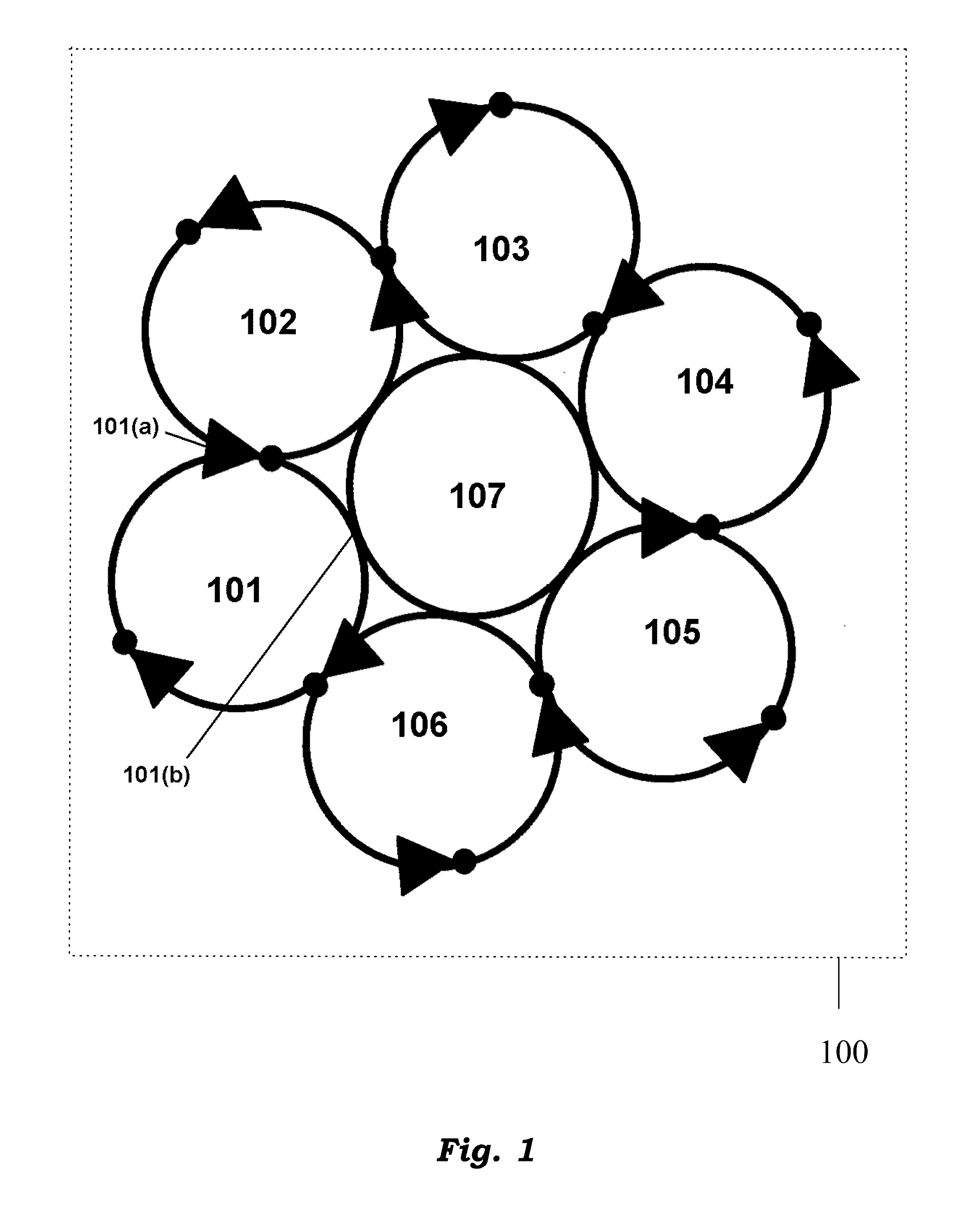
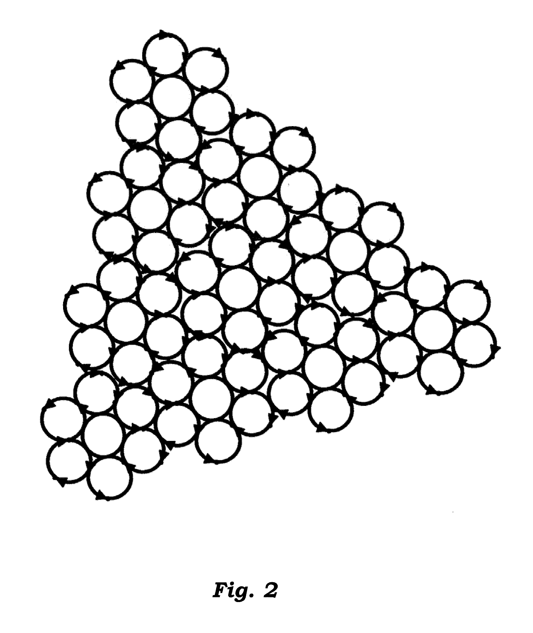
[0006]The various embodiments of the present disclosure pertain to an oscillator having a plurality of ring oscillators arranged in a hyper matrix structure. The ring oscillators constituting the oscillator in the present disclosure are either identical ring oscillators or non-identical oscillators. The ring oscillators are operatively coupled to each other either by a common inverter or tail current transistors. The plurality of ring oscillators works in synchronization and converges to a nominal frequency with a nominal phase. In accordance with the principle of synchronization, any shift in the nominal phase and frequency is resisted by the set of oscillators in unison. Therefore, the hyper matrix structure of a plurality of ring oscillators increases power dissipation at a particular frequency using simple VCOs or CCOs or both, and it reduces phase noise. There is no increase in the bias current per VCO, thus simplifying the design of the bias circuit.
[0008]According to another embodiment of the present disclosure, a system includes an oscillator wherein the oscillator has a plurality of operatively coupled ring oscillators arranged in a hyper-matrix structure. The operatively coupled ring oscillators are either identical or non-identical and are coupled through a common inverter or tail current transistors. Due to the arrangement of the ring oscillators in a hyper-matrix structure, the ring oscillators are synchronized and resist any variation in frequency or phase, thereby maintaining a consistent phase noise performance.
[0009]Another embodiment of the present disclosure refers to a method to improve the phase noise performance in an oscillator. The method includes operatively coupling of a plurality of ring oscillators in a hyper matrix structure. Such an arrangement in a hyper matrix structure ensures that the ring oscillators are synchronized and therefore, any variation in frequency or phase are avoided. Therefore, an efficient phase noise performance is achieved. The ring oscillators in the present embodiment are either identical or non-identical in nature.

Problems solved by technology

The total carrier power is multiplied by N2, however, uncorrelated noise power increases by N. Thus, the phase noise relative to the carrier decreases by a factor of N at the cost of a proportional increase in power dissipation.

Method used


Image

  • Matrix structure oscillator
  • Matrix structure oscillator
  • Matrix structure oscillator

Examples


Embodiment Construction

[0026]The embodiments of the present disclosure will be described in detail with reference to the accompanying drawings. However, the present disclosure is not limited to these embodiments. The present disclosure can be modified in various forms. The embodiments of the present disclosure described herein are only provided to explain more clearly the present disclosure to the ordinarily skilled in the art. In the accompanying drawings, like reference numerals are used to indicate like components.

[0027]The terms identical ring oscillators and non-identical ring oscillators have been used throughout the disclosure. Identical ring oscillators indicate that all ring oscillators are of the same stage i.e., all ring oscillators are 3-stage ring oscillators or 5-stage ring oscillators etc. Non-identical ring oscillators indicate that all ring oscillators coupled to each other are of different stages i.e., a 3-stage ring oscillator is coupled to a 5-stage ring oscillator which is further cou...


PUM


Abstract

An oscillator having a plurality of operatively coupled ring oscillators arranged in hyper-matrix architecture. The operatively coupled ring oscillators are either identical or non-identical and are coupled through a common inverter or tail current transistors. Due to the arrangement of the ring oscillators in a hyper-matrix structure, the ring oscillators are synchronized and resist any variation in frequency or phase thereby maintaining a consistent phase noise performance

Description

BACKGROUND[0001]1. Technical Field[0002]The present disclosure relates to oscillators and, more specifically, to hyper matrix structure oscillators.[0003]2. Description of the Related Art[0004]Of various existing applications, ring oscillators are a prime component in VCOs (Voltage Controlled Oscillators) and CCOs (Current Controlled Oscillators) and are used as clock generators to provide a desired frequency. However there are fluctuations in phase during the operation of a ring oscillator as a clock generator. This results in phase noise, which hinders efficient frequency generation.[0005]To increase the phase noise performance, an increased bias current is required, which further requires an increase in area. MEMS- and LC-based oscillators may be used; however, these oscillators require substantial topographical area and are costly in terms of manufacture and current consumption.BRIEF SUMMARY[0006]The various embodiments of the present disclosure pertain to an oscillator having a...

Claims


Application Information

Patent Timeline
IPC IPC(8): H03K3/03
CPCH03K3/0315H03B5/08H03L7/0995H03B2200/009H03B5/32
Inventor DUBEY, PRASHANT
Owner STMICROELECTRONICS INT NV
Why Eureka
Try Eureka