

Non-reciprocal circuit device
a circuit device and non-reciprocal technology, applied in waveguide devices, basic electric elements, electrical apparatus, etc., can solve the problems of primarily generated heat and deteriorating electrical characteristics of isolators, and achieve the effect of preventing deterioration of electrical characteristics and reducing hea
- Summary
- Abstract
- Description
- Claims
- Application Information
AI Technical Summary
Benefits of technology
Problems solved by technology
Method used
Image

Examples
Embodiment Construction
[0022]A non-reciprocal circuit device according to a first preferred embodiment of the present invention will now be described below with reference to the accompanying drawings.
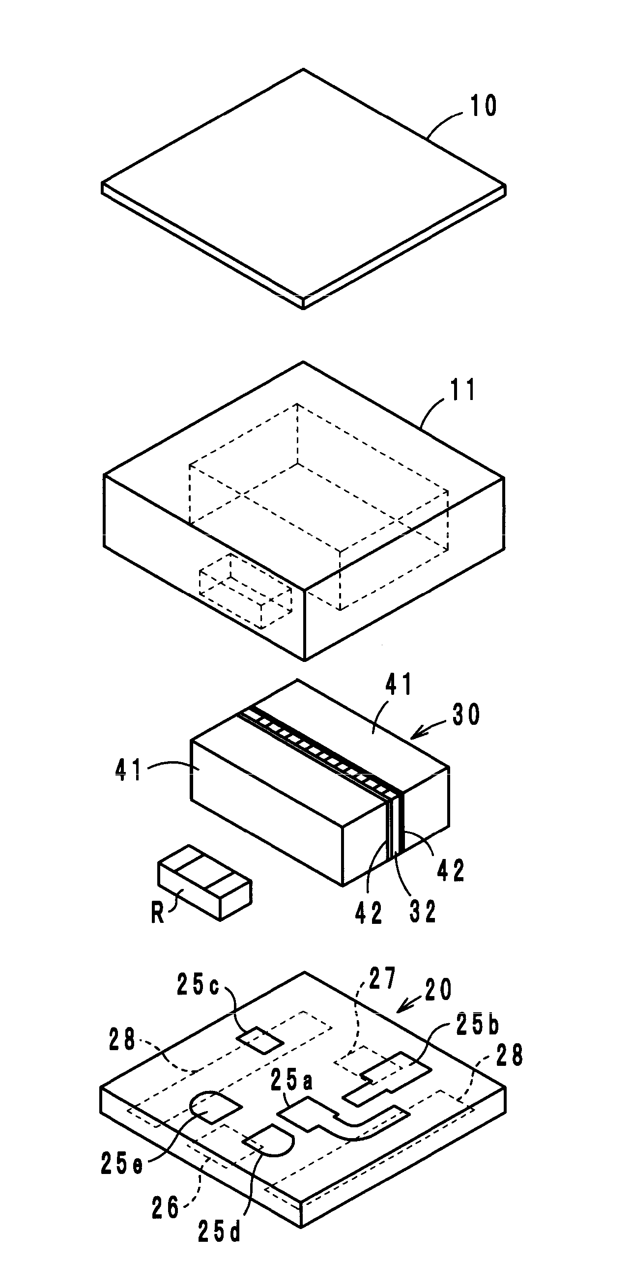
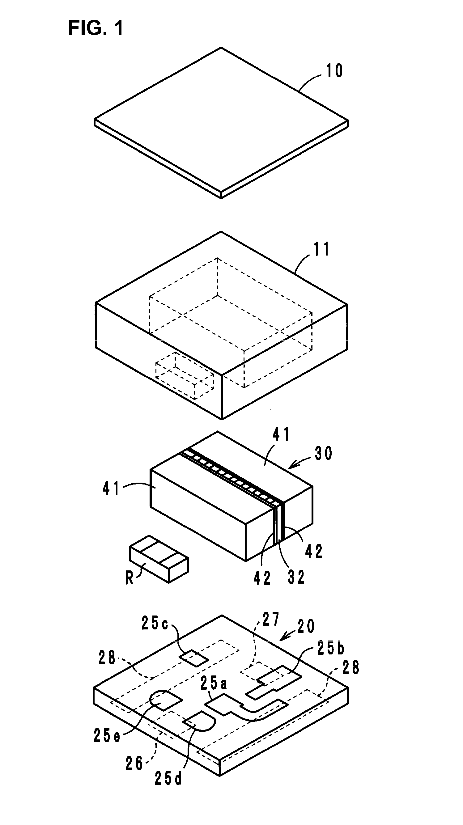
[0023]FIG. 1 shows an exploded perspective view of a 2-port type isolator according to a first preferred embodiment of the present invention. The 2-port type isolator is preferably a lumped constant type isolator, which preferably includes a tabular yoke 10, a circuit board 20, a ferrite-magnet assembly 30 which includes a ferrite 32 and a pair of permanent magnets 41.
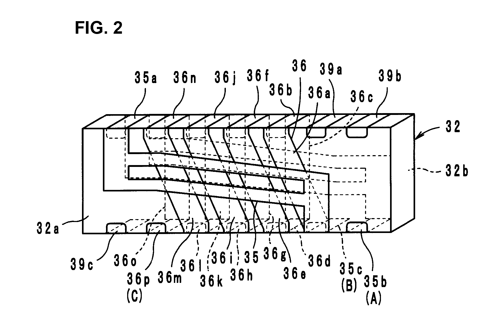
[0024]As shown in FIG. 2, a first central electrode 35 and a second central electrode 36, which are electrically insulated from one another, are arranged on front and back main surfaces 32a and 32b of the ferrite 32. The ferrite 32 preferably has a substantially rectangular parallelepiped shape having the first main surface 32a and the second main surface 32b arranged parallel or substantially parallel to each other, for example.
[0025]The perman...
PUM
 Abstract
Description
Claims
Application Information