
Digital direct conversion receiving apparatus and method

a receiving apparatus and digital technology, applied in the field of digital direct conversion receiving apparatus and method, can solve the problems of ineffective sampling scheme based on carrier frequency and affect the digital domain

Inactive Publication Date: 2010-06-24
ELECTRONICS & TELECOMM RES INST +1
View PDF17 Cites 58 Cited by
  • Summary
  • Abstract
  • Description
  • Claims
  • Application Information

AI Technical Summary

Benefits of technology

[0011]Example embodiments may provide a digital direct conversion receiving apparatus and method which may perform universal access by reconstructing a signal processing algorithm without a hardware change of the digital direct conversion receiving apparatus, when a arbitrary signal in a Radio Frequency (RF) band is down-converted.
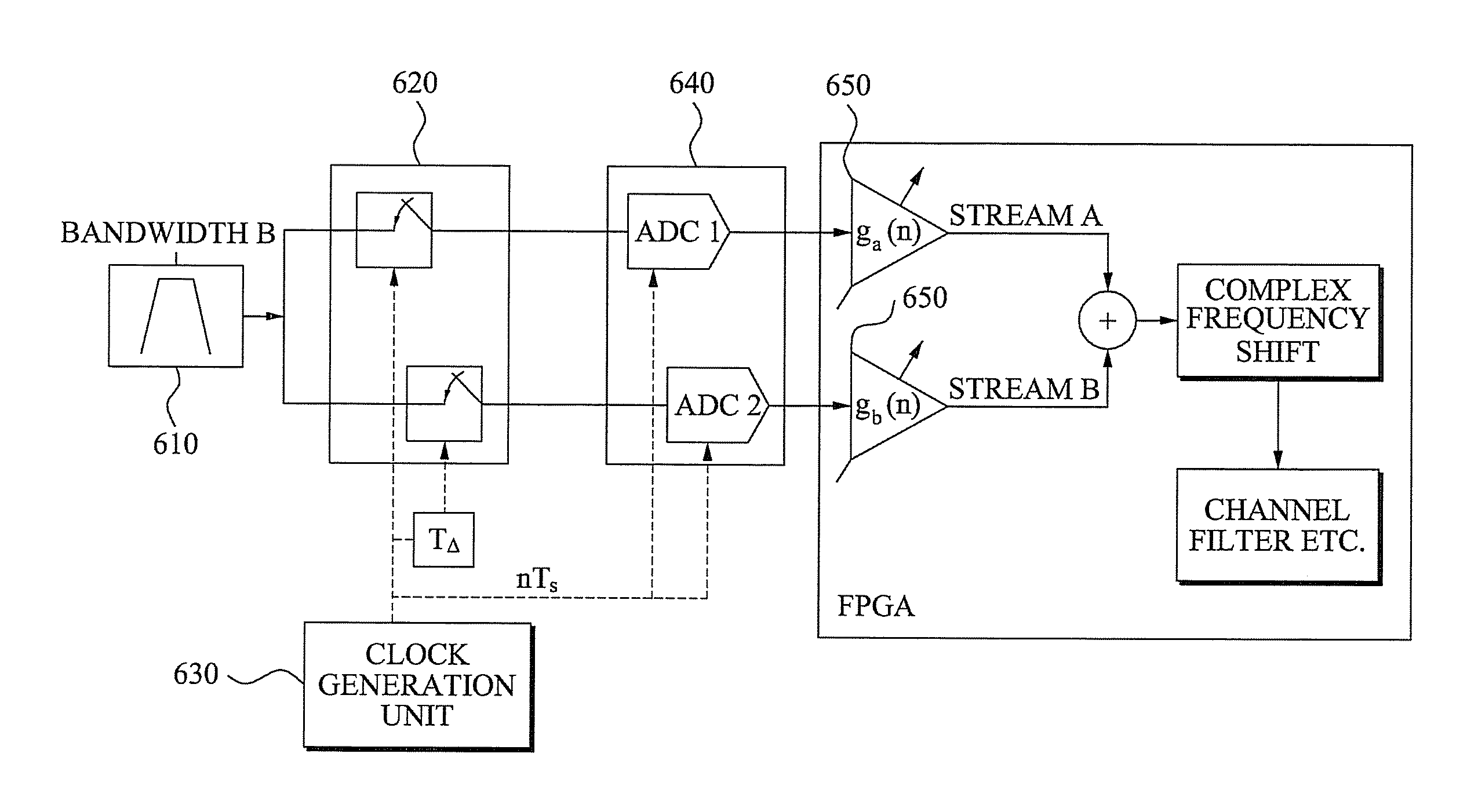
[0013]Example embodiments may also provide a digital direct conversion receiving apparatus and method which may generate clock signals having a time difference, generate a certain phase difference among sample streams, and thereby may remove an image component from the sample streams.
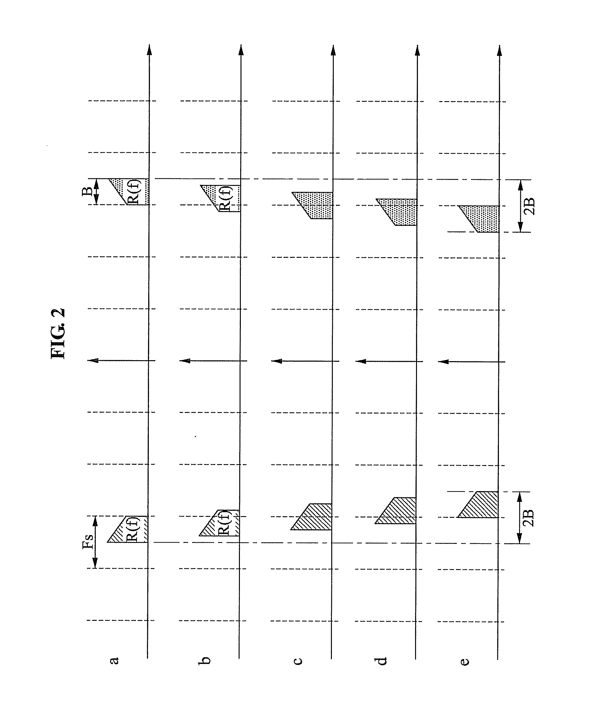
[0014]Example embodiments may also provide a digital direct conversion receiving apparatus and method which may enable a digitization unit to be operated at a sampling rate being at least twice as wide as a bandwidth of an RF signal, enable only an nth copy component of spectrum copy components generated by sampling to be shown in a baseband, and thereby may use an identical interpolant.
[0015]Example embodiments may also provide a digital direct conversion receiving apparatus and method which may down-convert an RF signal into an intermediate frequency band adjacent to a frequency of ‘0’, and thereby may avoid an effect of a Direct Current (DC) offset.
[0037]Also, according to example embodiments, a digital direct conversion receiving apparatus and method may generate clock signals having a time difference, generate a certain phase difference among sample streams, and thereby may remove an image component from the sample streams.
[0039]Also, according to example embodiments, a digital direct conversion receiving apparatus and method may down-convert an RF signal into an intermediate frequency band adjacent to a frequency of ‘0’, and thereby may avoid an effect of a Direct Current (DC) offset.

Problems solved by technology

Accordingly, a sampling scheme based on a carrier frequency may be ineffective and affect a digital domain due to a significant amount of data.

Method used


Image

  • Digital direct conversion receiving apparatus and method
  • Digital direct conversion receiving apparatus and method
  • Digital direct conversion receiving apparatus and method

Examples


Embodiment Construction

[0049]Reference will now be made in detail to example embodiments, examples of which are illustrated in the accompanying drawings, wherein like reference numerals refer to the like elements throughout. Example embodiments are described below to explain the present disclosure by referring to the figures.

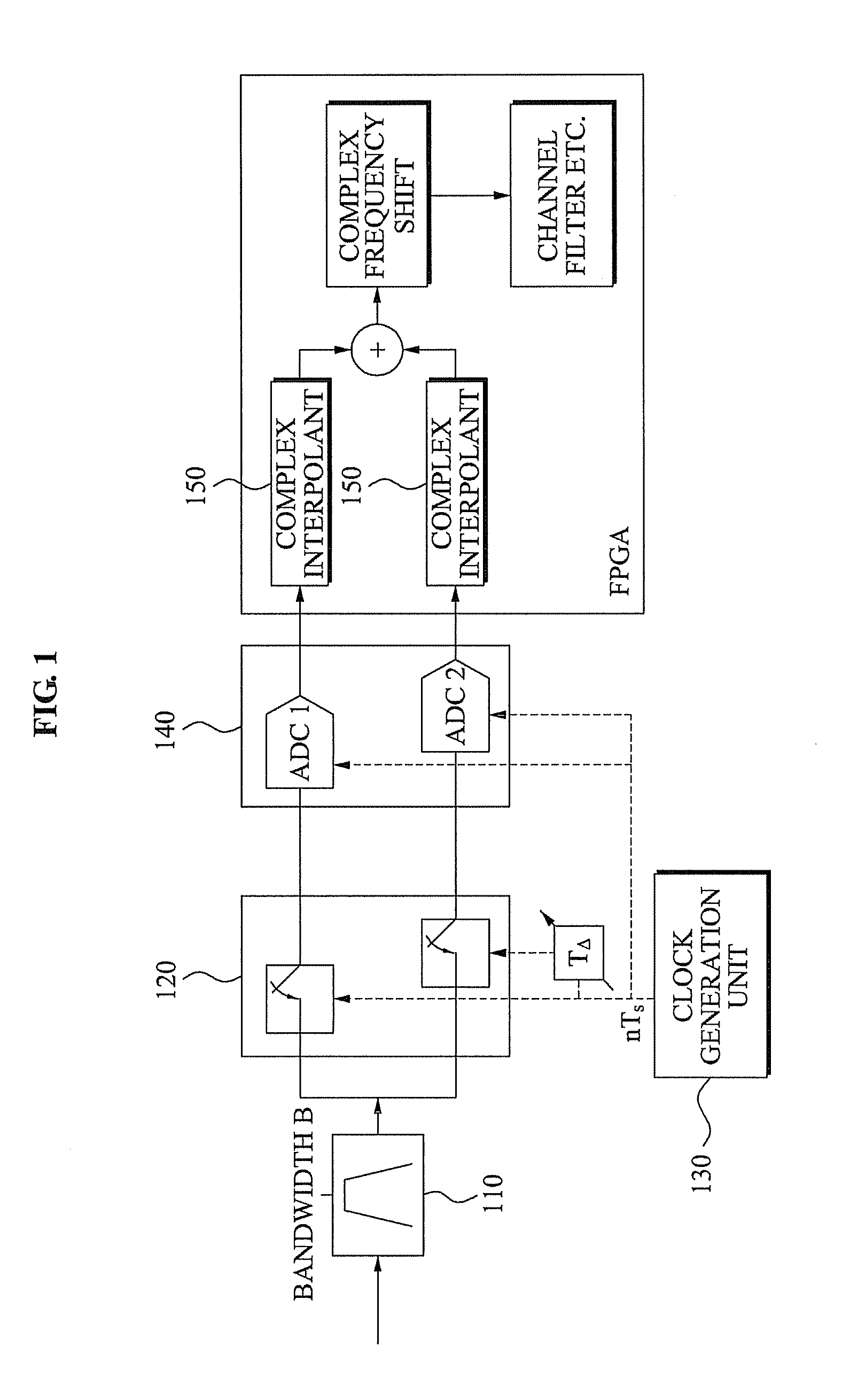
[0050]FIG. 1 illustrates a digital direct conversion receiving apparatus according to example embodiments.

[0051]The digital direct conversion receiving apparatus may include a tunable Radio Frequency (RF) filter 110, a phase conversion unit 120, a clock generation unit 130, a digitization unit 140, and a complex interpolant 150.

[0052]The tunable RF filter 110 may select only an RF signal to be down-converted, from RF signals received from an antenna, and remove an aliasing component and a noise of the selected RF signal. That is, the tunable RF filter 110 may function as a Low Noise Amplifier (LNA) and a Band-Pass Filter (BPF).

[0053]The tunable RF filter 110 may have a baseband of the...


PUM


Abstract

A digital direct conversion receiving apparatus, including: a phase conversion unit to down-convert a Radio Frequency (RF) signal into a plurality of sample signals, and generate a certain phase difference among the plurality of sample signals when the RF signal is down-converted; and a variable complex gain unit to remove an image component from the plurality of sample signals using the generated phase difference.

Description

CROSS-REFERENCE TO RELATED APPLICATION[0001]This application claims the benefit of Korean Patent Application No. 10-2008-0130893, filed on Dec. 22, 2008, in the Korean Intellectual Property Office, the disclosure of which is incorporated herein by reference.BACKGROUND[0002]1. Field[0003]Example embodiments relate to a digital direct conversion receiving apparatus and method.[0004]2. Description of the Related Art[0005]When a Radio Frequency (RF) signal which is an analog signal is received, a sampling frequency which is at least twice a carrier frequency is required to enable an existing sampling theory to be applied. In general, however, a bandwidth where a signal exists may be 0.003 to 0.2% of a carrier frequency. Accordingly, a sampling scheme based on a carrier frequency may be ineffective and affect a digital domain due to a significant amount of data.[0006]A Band-Pass Sampling (BPS) scheme has been provided to overcome such disadvantages. In a BPS scheme, a sampling frequency ...

Claims


Application Information

Patent Timeline
Patent Type & Authority Applications(United States)
IPC IPC(8): H03M1/12
CPCH03M1/12H04L27/142H04L2027/0051H04L2027/0026H04L27/3881H04B1/10
Inventor KIM, HYUNG JUNGKIM, JAE HYUNG
Owner ELECTRONICS & TELECOMM RES INST
Learn More