Input device and data processing system

a technology of input device and data processing system, which is applied in the direction of static indicating device, instruments, devices characerised by mechanical means, etc., can solve the problems of limited number of dials or switches that can be provided to the main body (housing) of input device, difficult stably operation of dials or switches, and limitation of multi-functional capability of three-dimensional input devices. achieve enhanced convenience of three-dimensional input devices, excellent operating properties, and high convenien

Active Publication Date: 2010-06-24
SEIKO EPSON CORP
View PDF5 Cites 26 Cited by
  • Summary
  • Abstract
  • Description
  • Claims
  • Application Information

AI Technical Summary

Benefits of technology

[0044]The convenience of a three-dimensional input device is enhanced through the use of at least one of the aspects of the present invention described above. The use of three-dimensional space is becoming more common in computers, and accordingly there is currently an increasing need for a hig

Problems solved by technology

However, since the input device is used while being held in space by the user, a dial or switch is difficult to stably operate.
Consequently, the number of dials or switches that can be provided to the main body (housing) of the input device is limited.
This limitation is an obstacle to adding multifunction capability to a three-dimensional input device.
As described above, since an input device is used while being held in space in the hand of a user, a dial or switch is difficult for the user to stably operate, but the user can easily rotate the

Method used


Image

  • Input device and data processing system
  • Input device and data processing system
  • Input device and data processing system

Examples


first embodiment

Example of Three-Dimensional Input Device

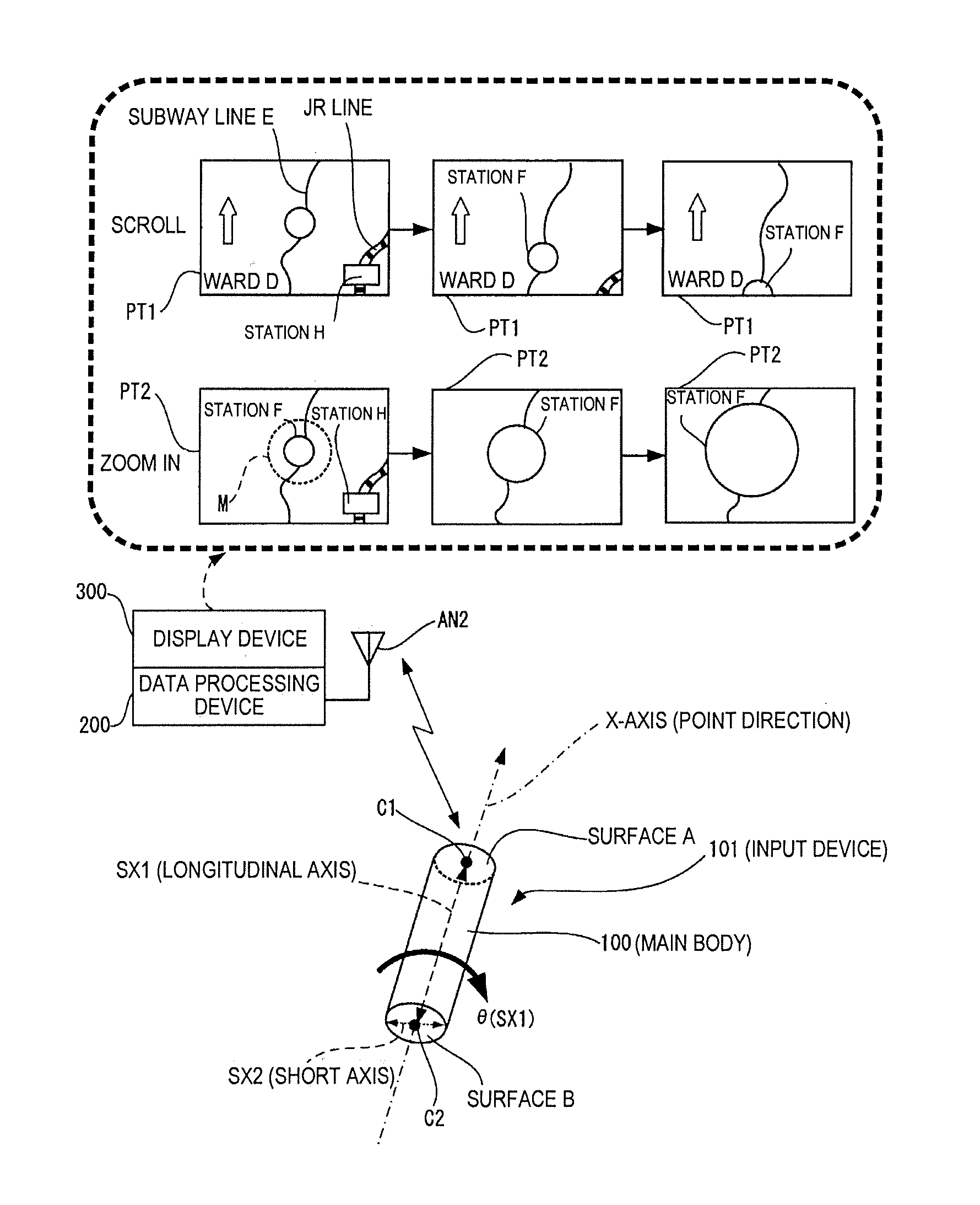
[0064]FIG. 1 is a view showing an example of the configuration of a data processing system that utilizes an input device (in this instance, a three-dimensional input device is a pointing device that can be used instead of a mouse or laser pointer, for example).

[0065]In FIG. 1, a data processing system is formed by an input device 101, a data processing device 200 (having a wireless antenna AN2), and a display device 300. The input device 101 and the data processing device 200 can transmit and receive signals (information) by communication (wireless communication in this instance; however, this configuration is not limiting, and wired communication, optical communication, or the like may be used).

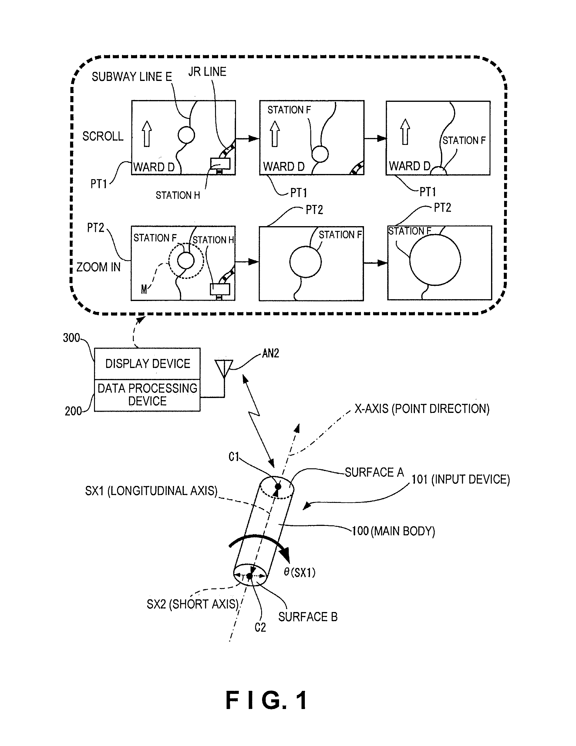
[0066]The input device 101 has a longitudinal axis (long axis) SX1 and a motion sensor unit (not shown in FIG. 1). The motion sensor unit has an angular velocity sensor (e.g., a gyroscope), an acceleration sensor, or the like, for example, and can det...

second embodiment

[0148]FIGS. 14 through 16 are views showing examples of the external structure of other examples (in which an enable switch or the like is provided) of an input device for detecting rotation about the X-axis, rotation about the Y-axis, and rotation about the Z-axis.

[0149]In FIG. 14, the main body (housing) 100 of the input device 101 is provided with an operating unit 700 having an output enable switch SW1 (e.g., a press-type or slide-type switch) for switching between enabling and disabling signal output.

[0150]In this instance, a case is assumed in which the input device 101 has a cursor pointer movement control function (first control input function) and a display screen scrolling function (second control input function). The output enable switch SW1 shown in FIG. 14 is a shared output enable switch for controlling the enabling / disabling of each function in common. Since the output enable switch SW1 can be operated independently of the orientation of the main body (housing) 100 in...


PUM


Abstract

An input device includes a main body and a motion sensor unit. The main body has a longitudinal axis. The motion sensor unit is configured and arranged to detect rotation of the main body about the longitudinal axis. The motion sensor unit has an X-axis angular velocity sensor configured and arranged to detect an angular velocity of the main body about an X-axis in a three-dimensional orthogonal coordinate system defined by the X-axis, a Y-axis and a Z-axis. The X-axis coincides with the longitudinal axis of the main body and the Y-axis and the Z-axis being orthogonal to each other in a first plane perpendicular to the X-axis.

Description

CROSS-REFERENCE TO RELATED APPLICATIONS[0001]This application claims priority to Japanese Patent Application No. 2008-321909 filed on Dec. 18, 2008. The entire disclosure of Japanese Patent Application No. 2008-321909 is hereby incorporated herein by reference.BACKGROUND[0002]1. Technical Field[0003]The present invention relates to an input device and to a data processing system.[0004]2. Related Art[0005]The need has recently increased for a system that utilizes an input device for generating and outputting a physical quantity signal in accordance with the motion of a main body (including at least one of the orientation (including rotation) of the main body (housing) and the movement (including translational movement) of the main body) in space (e.g., a three-dimensional mouse or the like).[0006]Japanese Laid-Open Patent Publication No. 2001-56743, for example, discloses a technique that utilizes a button-operated input device in which a cursor pointer is moved on an image display d...

Claims


Application Information

Patent Timeline
IPC IPC(8): G06F3/033G01P3/00G06F15/00G06F3/0346G06F3/038
CPCG06F3/0346
Inventor NAKAOKA, YASUSHI
Owner SEIKO EPSON CORP
Why Eureka
Try Eureka