
Wave making device

a technology of artificial waves and making devices, which is applied in the field of artificial wave making devices, can solve the problems of high energy consumption of devices, high cost of devices, and large investment, and achieve the effect of low energy consumption

Inactive Publication Date: 2010-06-24
WOW!
View PDF4 Cites 7 Cited by
  • Summary
  • Abstract
  • Description
  • Claims
  • Application Information

AI Technical Summary

Benefits of technology

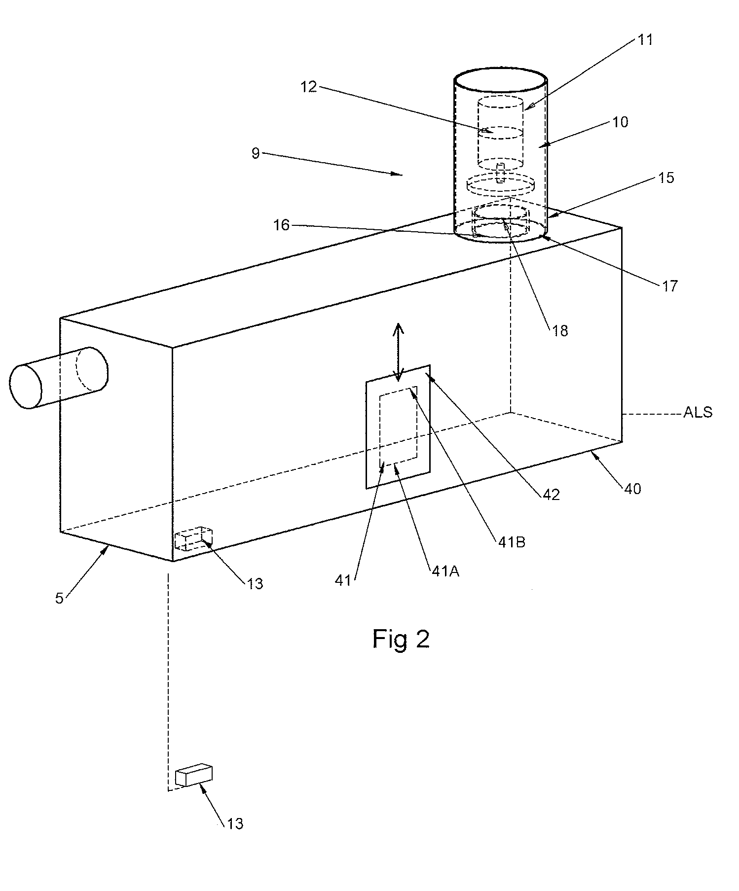
[0029]According to another detail of an embodiment, the ratio open surface of the exhaust valves or valves expressed in cm2 / volume of the upper portion of the caisson is greater than 0.0005, advantageously greater than 0.001, preferably comprised between 0.005 and 0.05. With such a ratio, it is possible to ensure a rapid exhaust of air from the caisson.
[0031]According to a further detail of an advantageous embodiment, the bottom of the caisson is open, said bottom being provided with a series of elements defining passages with a maximum width or diameter of less than 10 cm. The bottom is for example provided with a open grid for preventing the passage of large object into the caisson.
[0037]This is advantageous for controlling the good working of the blower and of the exhaust valve(s) from time to time.

Problems solved by technology

Said devices have high energy consumption and require great investment, so it is not suitable for aquatic breeding.
However, the wave generated by said device is still based on the method of forced vibration.
Therefore, said device has to be provided with an air-blow of great output power, and the cost of the device is still high.
The use of such a large number of valves increases the risk of mechanical problems, as well as the problem of correct control of the timing of the closing or opening of the valves, whereby causing variation which are detrimental for achieving the desired wave pattern.
Furthermore, as the blower is intended to suck periodically air from the chamber, so that liquid flows into the chamber, a risk exists that water or water droplets are sucked into the blower, causing then problems of corrosion, growth of bacteria, etc.

Method used


Image

  • Wave making device
  • Wave making device
  • Wave making device

Examples


Embodiment Construction

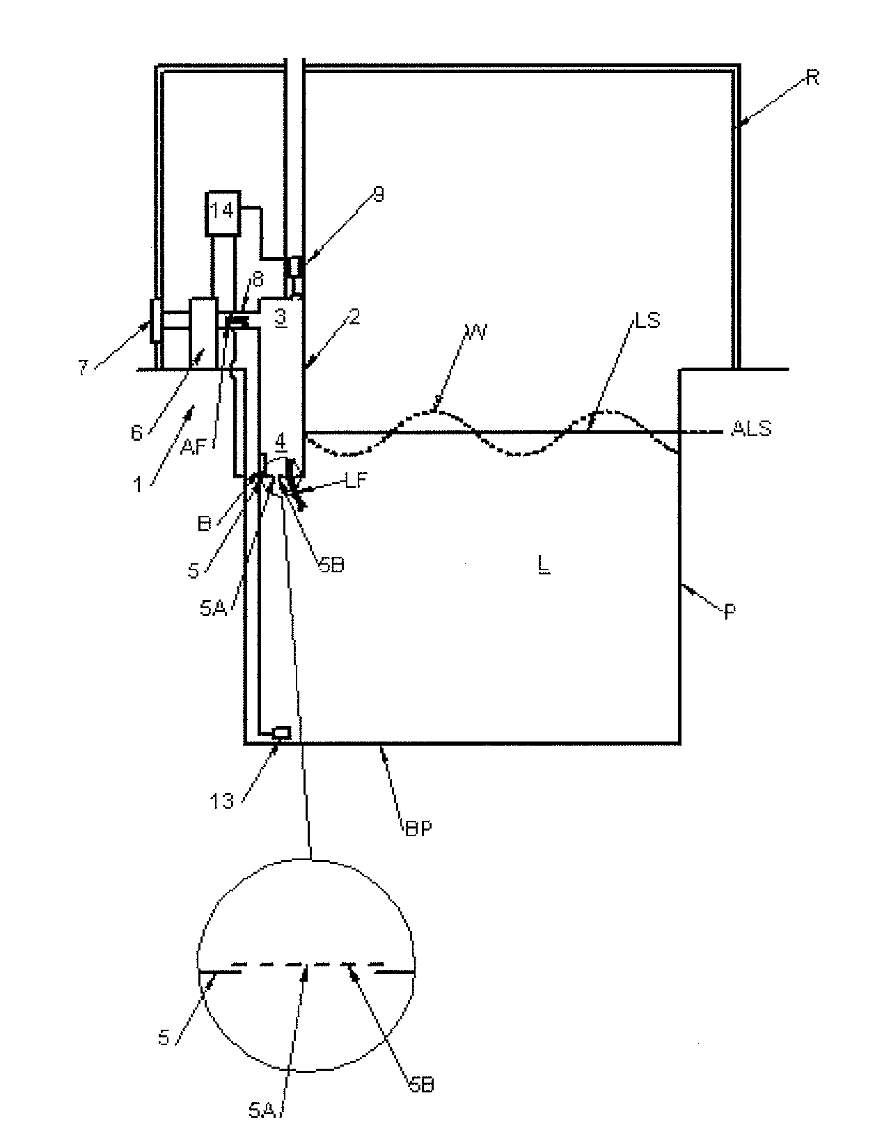
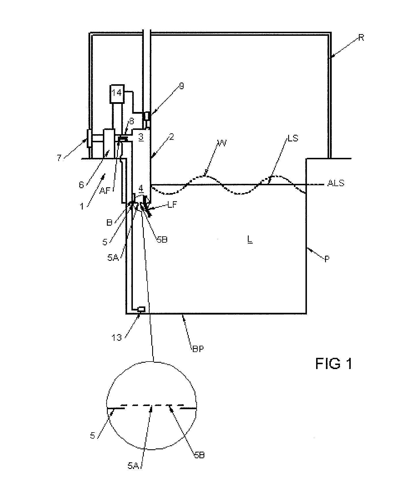
[0063]FIG. 1 is a schematic view of an adaptive control artificial wave making device 1 for generating wave W with at least one specific wave pattern, at least at the surface LS of a liquid L contained into a pool P located in a room R with an air containing atmosphere having an ambient pressure. The surface LS of the liquid has an average liquid level ALS. The pool P is for example a swimming pool, a treatment basin, an aeration / oxygenation treatment pool, an aquarium, etc. The wave height generated by the device is advantageously lower than 100 cm, preferably lower than 50 cm, said height being the difference between the maximum level achieved by the wave and the average liquid level in the pool.

[0064]The wave making device 1 comprises at least:[0065]a caisson 2 adapted to be mounted at least partly into the pool P containing the liquid L possibly with some foam. The caisson 2 having at least an upper portion 3 located above the average liquid level ALS and a bottom portion 4 inte...


PUM


Abstract

The wave making device comprises a caisson connected to an air blower and to a control valve mechanism comprising an exhaust valve adapted to move between a closed position and an open position, and a system adapted to move the exhaust valve and to maintain said exhaust valve into said position. The control valve mechanism is adapted to ensure continuously an air pressure within the caisson at least equal to the atmospheric pressure.

Description

FIELD OF THE INVENTION[0001]The present invention relates to an artificial wave making device, and to a process for making artificial wave at the surface of a pool.BACKGROUND OF THE INVENTION[0002]Artificial wave making devices are commercialized by the company “WOW Company”. Said devices comprises a floating spherical element in which a system moves at least one body so as generate downwards and / or upwards movement of the floating spherical element, whereby generating artificial wave at the surface of the pool.[0003]Artificial wave making devices have also been developed by using a high flow and high pressure air-blower to blow or draw air periodically in a given frequency to form waves. If the area of a pool is about 700 m2, an air-blower having output power of 165 kW is required. Said devices have high energy consumption and require great investment, so it is not suitable for aquatic breeding.[0004]U.S. Pat. No. 4,730,355 to Mark L, Kreinbihl et al. discloses an artificial wavema...

Claims


Application Information

Patent Timeline
IPC IPC(8): F04D35/00
CPCE04H4/0006A01K63/006
Inventor DEMARTEAU, JOSEPH
Owner WOW!
Learn More